Table of Contents
May 3 – Electrical Systems Part 1
May 21 – Wood Working Part 1
May 29 – Wood Working Part 2
May 31 – Electrical Systems – Part 2
June 1 – Progress Pics
June 4 – Desoldering + Soldering
June 6 – Wood Working – Part 3
June 13 – Putting it all together
June 21 – Programming
November 7 – Feet + Polishing
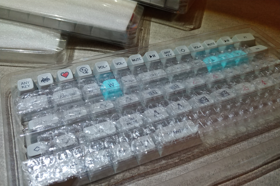
December 27 – Keycaps Arrive + Sound Test
Extras
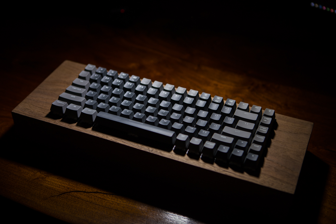
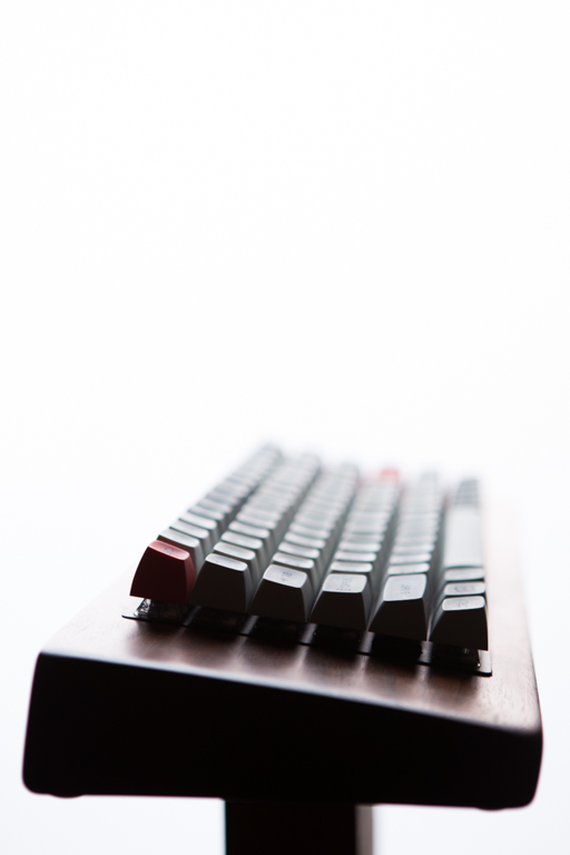
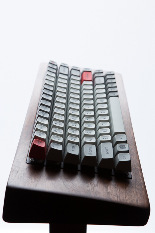
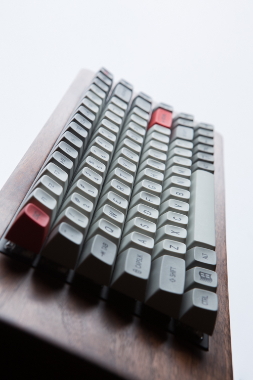
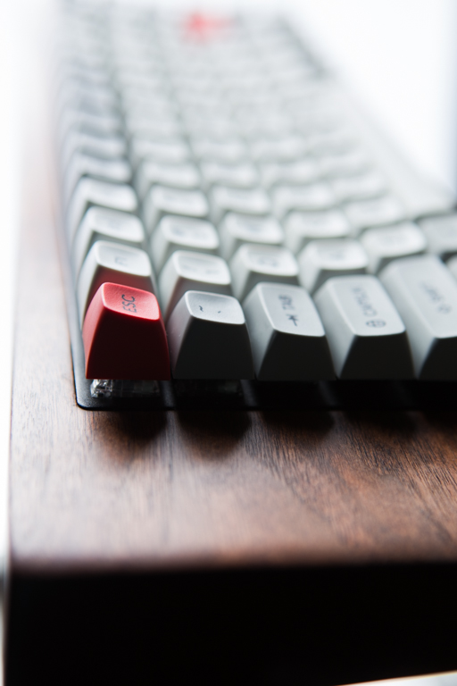
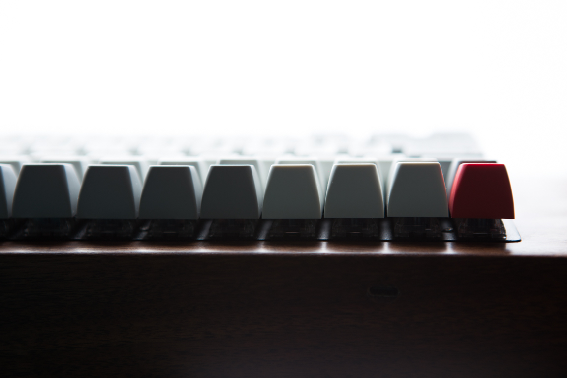
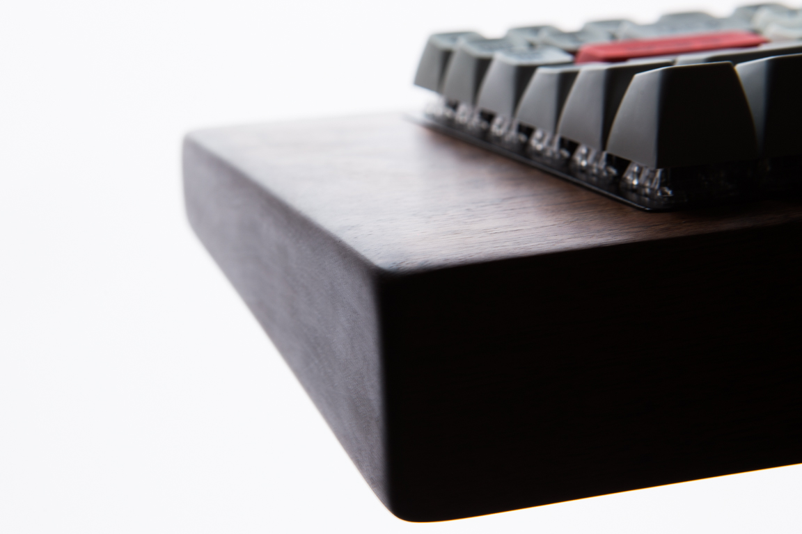
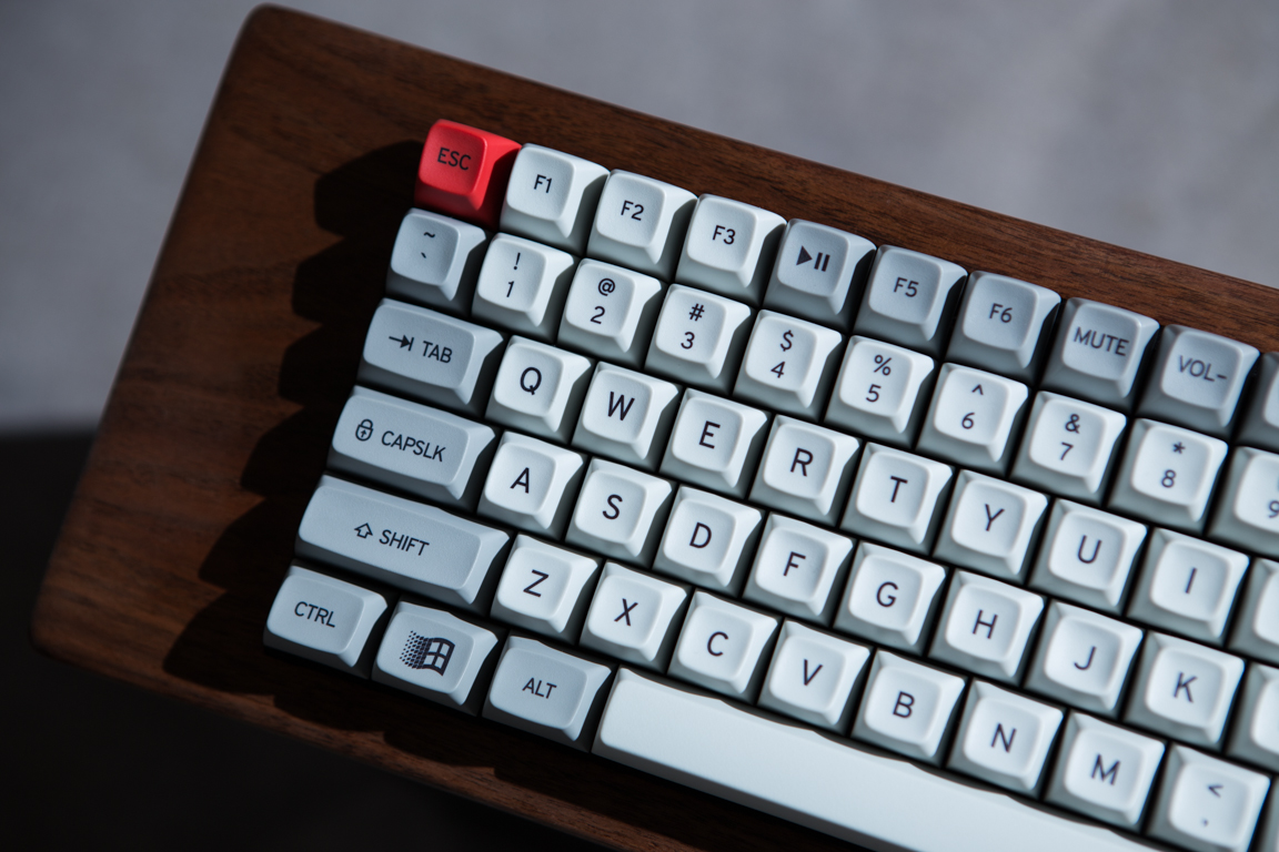
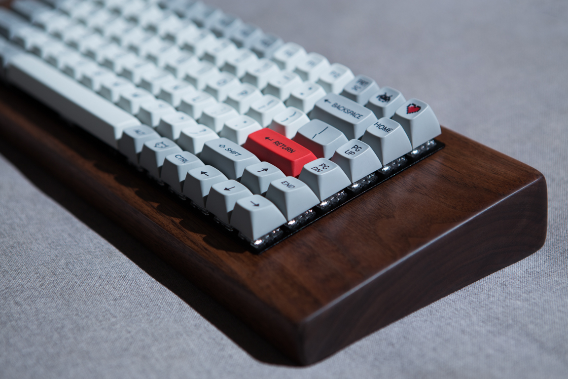
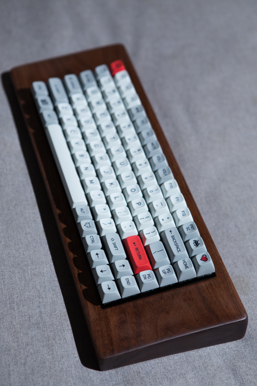
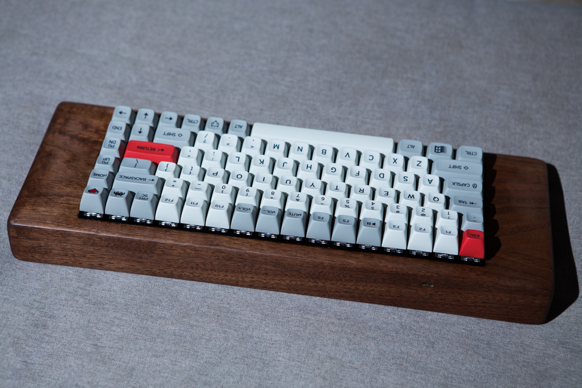
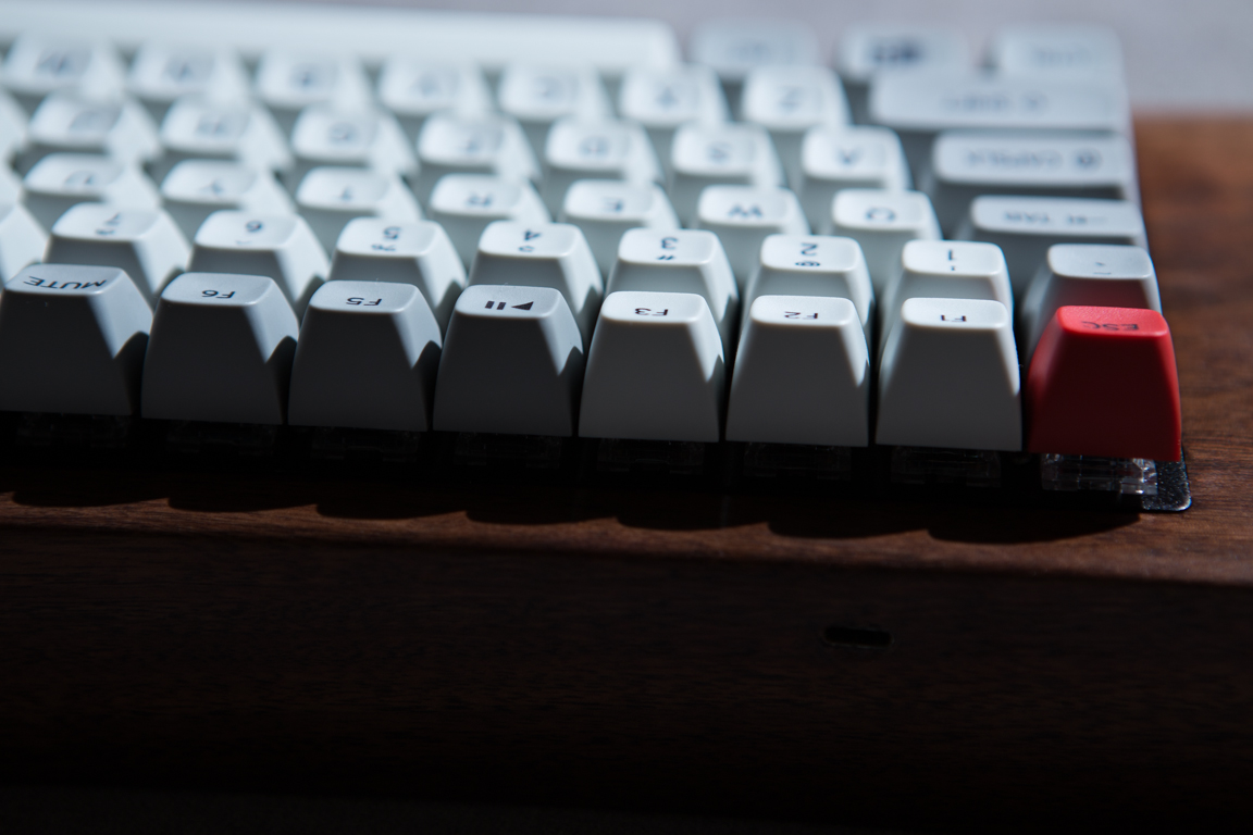
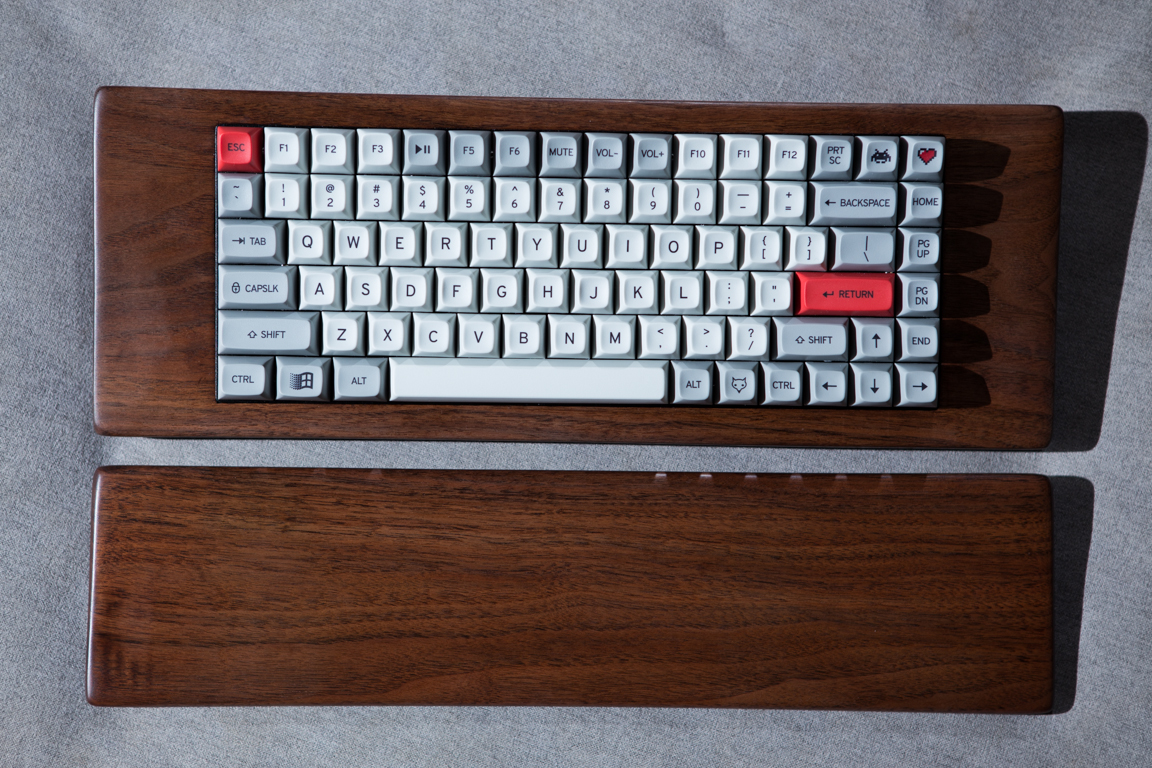
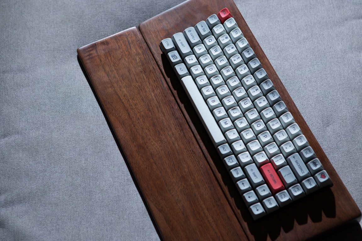
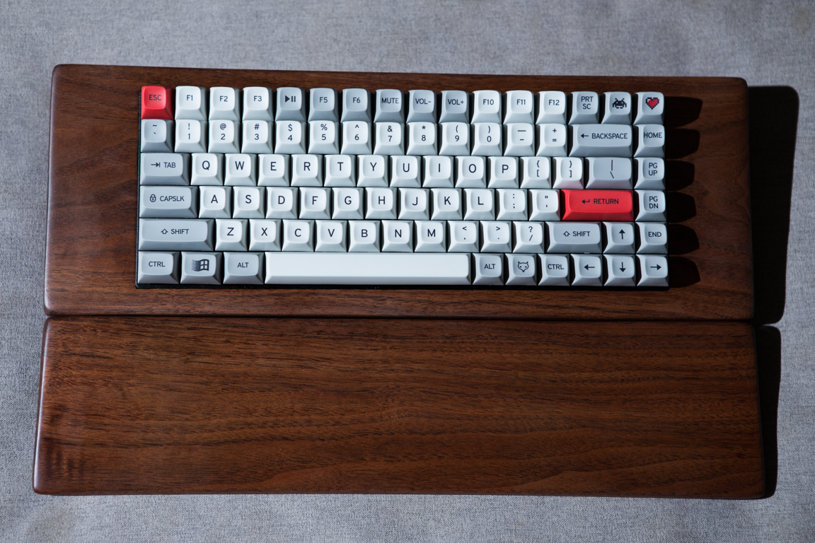
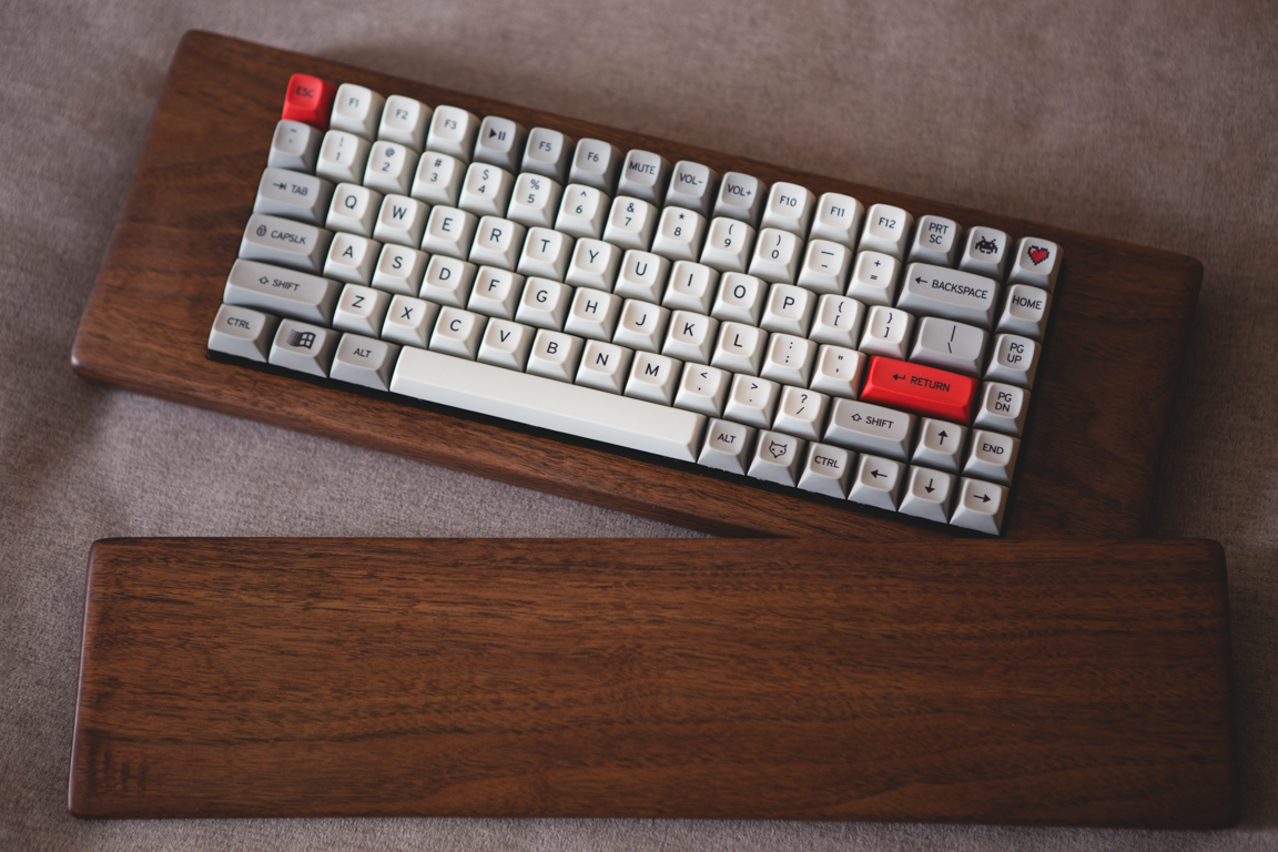
Glamour shots
Tools/Parts
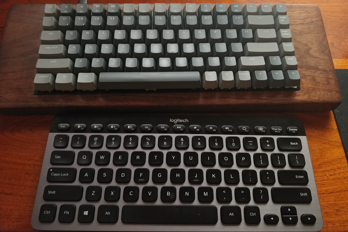
I recently purchased a Keychron K2 Mechanical Keyboard with Gateron Brown switches. Coming from the Logitech K810 Wireless Illuminated I wanted to upgrade to a better feeling keyboard. I went for the K810 due to it being one of the only wireless, illuminated, multi device keyboards at the time. It looked good but it never felt great typing. The K2 adds to the feature set of the K810 by adding mechanical switches, RGB lighting, and practical function keys. Yes, I enjoy having dedicated next(F9) and prev(F7) keys very much.
So far I am loving they K2. I never realized how hard I pressed keys in the past as I now find the Gateron Brown switches a bit too soft. This meant I would very easily bottom out and produce a loud clacking sound as the keycaps would resonate sound through to the plastic lower housing. To help fix this issue I ordered a set of rubber gaskets. They help quite a bit but I still feel the keyboard needs some upgrades.
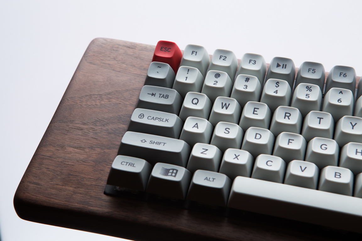
For starters the keycaps don’t feel great. They are made of an ABS (Acrylonitrile Butadiene Styrene) material. They are a bit slippery and do not grip my fingers well. I feel this material also adds to the high pitched clacking sound being produced when typing. For example when I press on the `caps lock` key I get a different sound than pressing on the alphanumeric keys (Same goes for the spacebar, etc). The gaskets helped a bit with this but I think there’s room for improvement. The I ordered a set of MT3 /dev/tty keycaps. MT3 is the profile (shape of keys) and /dev/tty is the colorway. The MT3 profile closely resembles SA. They are tall keycaps and are reminiscent of the old terminal keyboards. They’re made of PBT (Polybutylene Terephthalate) plastic and are shaped to cup your fingers as you type. You can read more about them here.
The next upgrade in the works is a custom case. I’ve browsed through /r/MechanicalKeyboards and I’m hoping to build something similar to this. I haven’t done much woodworking since wood shop classes back in high school so I’m a little nervous and excited. I tried looking for an already made keyboard case, but have no luck finding anything to fit the 75% form factor of the Keychron K2.
While upgrading the case I also thought I would upgrade the battery. The K2 comes with a 4000mAh battery. So far I’ve found it good for about 2-3 days of use (while the backlight is on). Would be great if I could expand this to a week or two as the K810 did have great battery life (it had a proximity sensor which turned the backlight off when no hands were near its surface).
May 3 (Electrical Systems – Part 1)
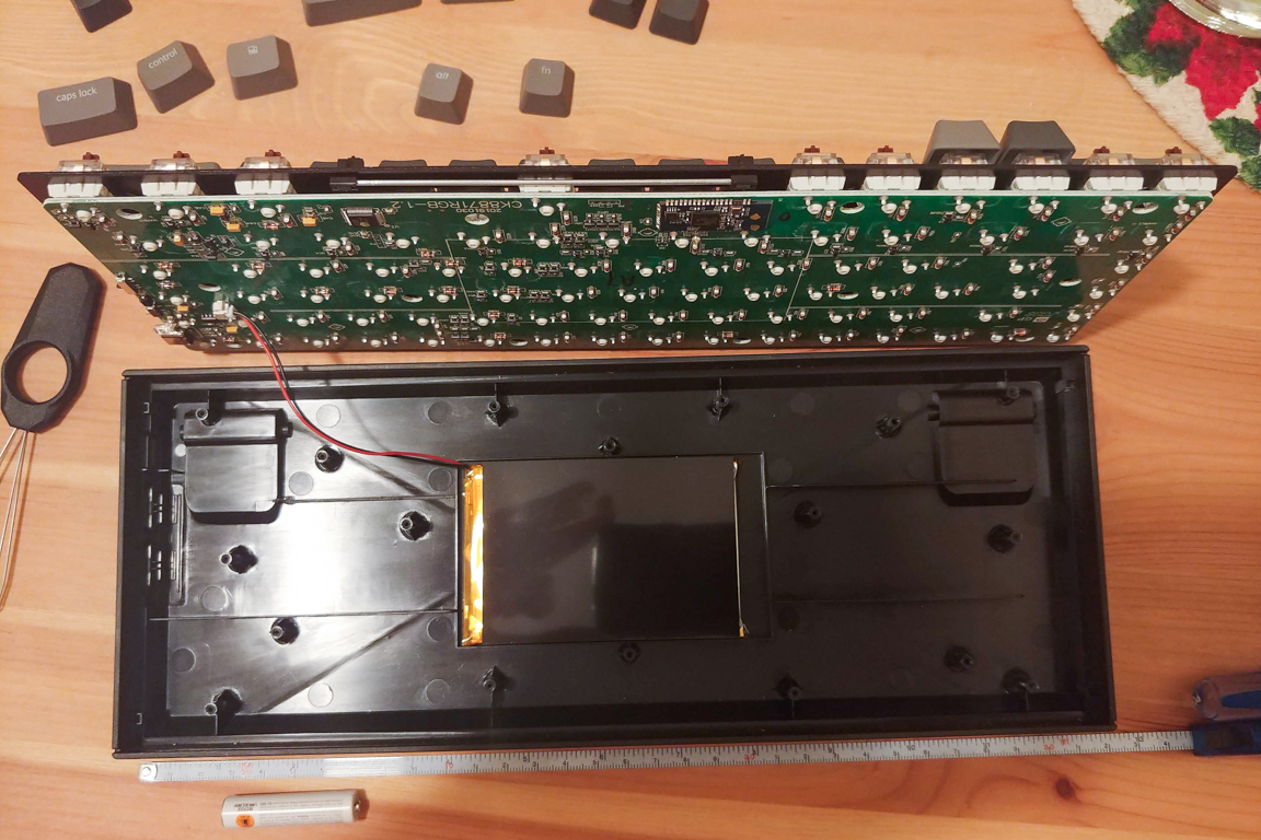
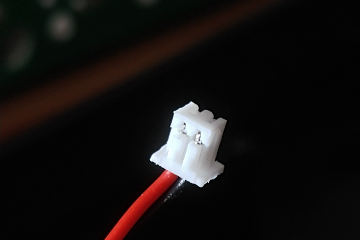
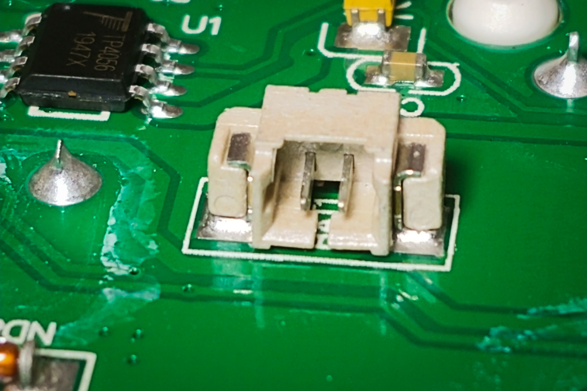
Now that I have the keyboard I decided to take it apart to see what I could do. It was relatively easy to disassemble. Keychron even has a guide on how to do it. I noticed that the battery was soldered to the plastic case. However, It was possible to disassemble the battery from the PCB by disconnecting the JST connection (I think its a JST PH connection).
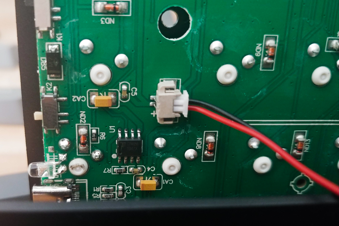
Per the manufacturer the standard battery’s capacity is 4000mAh, however I did not know the voltage. I started looking around on Ebay and Google and figured it was probably a 3.7V battery. To be sure I purchased a multimeter and confirmed my assumption was correct. I initially wanted to purchase Lithium Ion Batteries but thought they would be a little too big so I settled for Lithium polymer batteries as they are thinner and the keyboard came with one to begin with. I purchased two 10,000mAh batteries for a total capacity of 20Ah. This should last me about a week or so.
To charge the battery I initially wanted to get one of those USBC wireless charging plates, but from my previous experience using wireless charging technology the distance between the plates and the charging pad needs to be small (less than the thickness of some cases). Since I don’t want to sand the wood to that thinness I’m going to settle for a USB cable.
May 21 (Wood Working – Part 1)
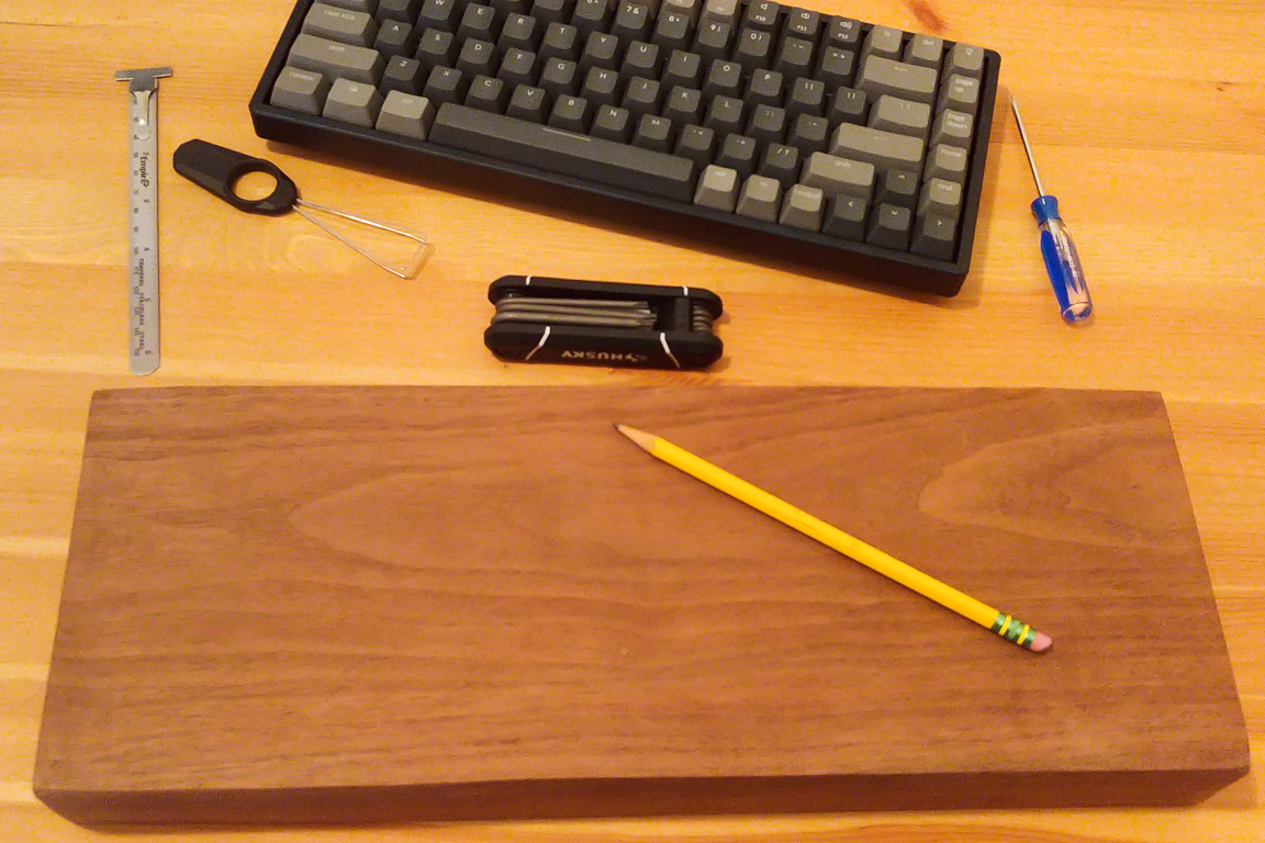
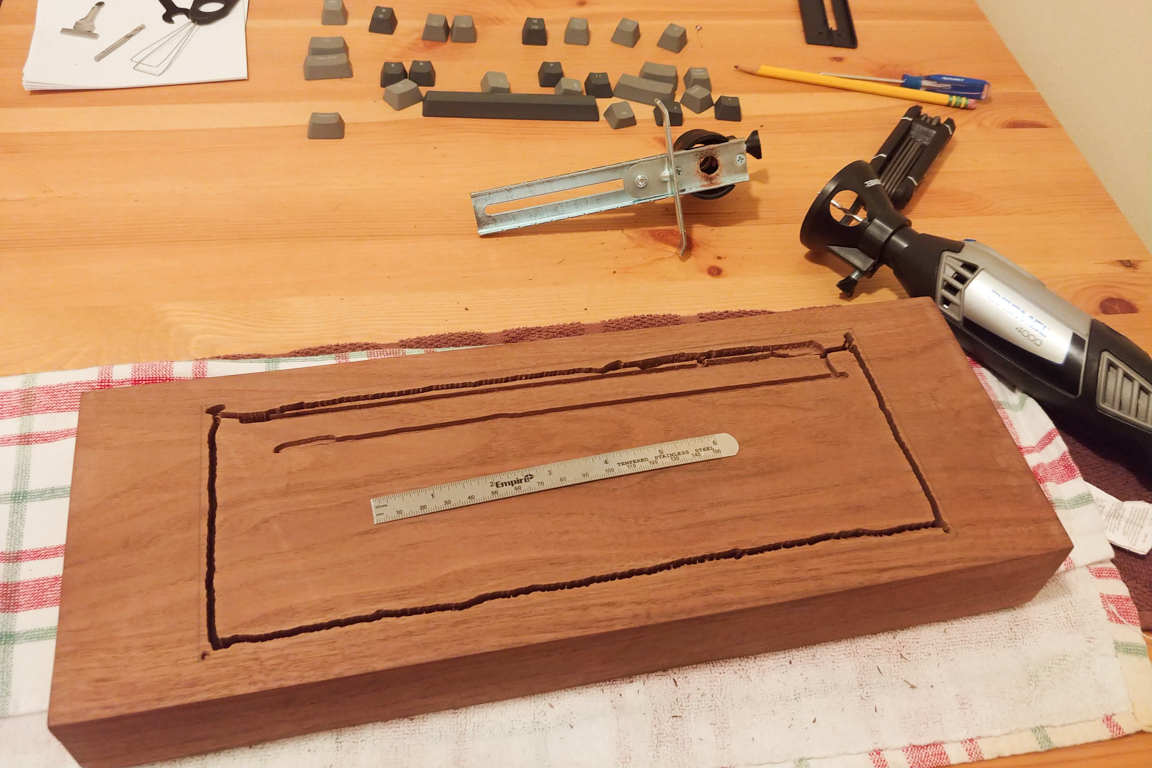
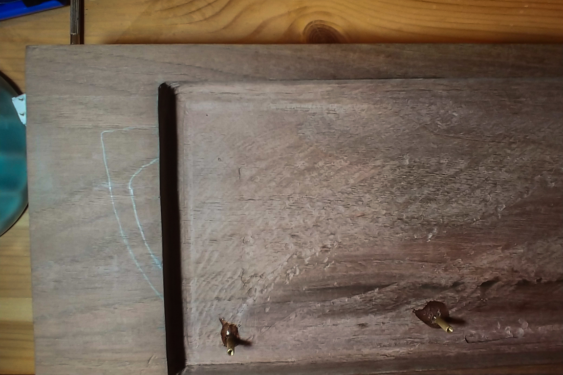
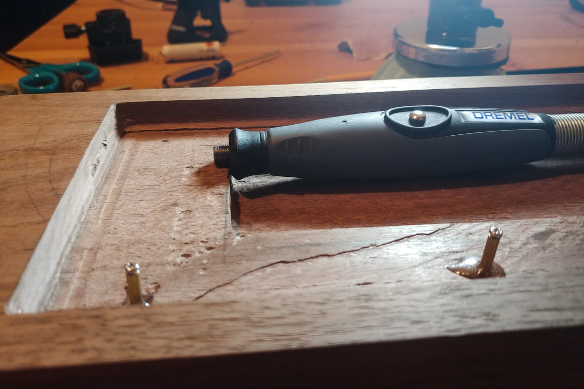
Now that I had the batteries decided on I had to start with the wood working. I scoured the internet (Ebay primarily) for some wood. I stumbled upon a listing for two blocks of Walnut wood for a pretty good price. I pulled the trigger, got a Dremel, safety goggles, mask, 6″ scale and got to work.
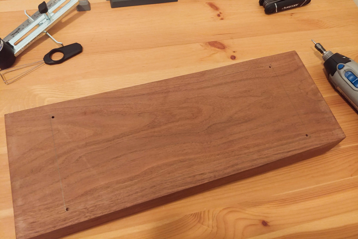
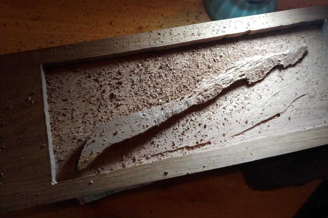
Having never used a Dremel I was really nervous. I measured the original black metal keyboard plate and drew an outline around the wood to represent my cutting surface. I then drilled some holes in the corners and planned to connect the dots.
This took much longer than expected. It took me about 3 days to get all this work done. But the end result is very satisfying to look at (and run my finger across). I still need to do a bunch of sanding and I plan to cut the bottom of the block at an angle so that the whole board is slanted towards me. I’ll be doing that once the batteries are installed. I also need to do some research on which finish to apply to the wood.

May 29 (Wood Working – Part 2)
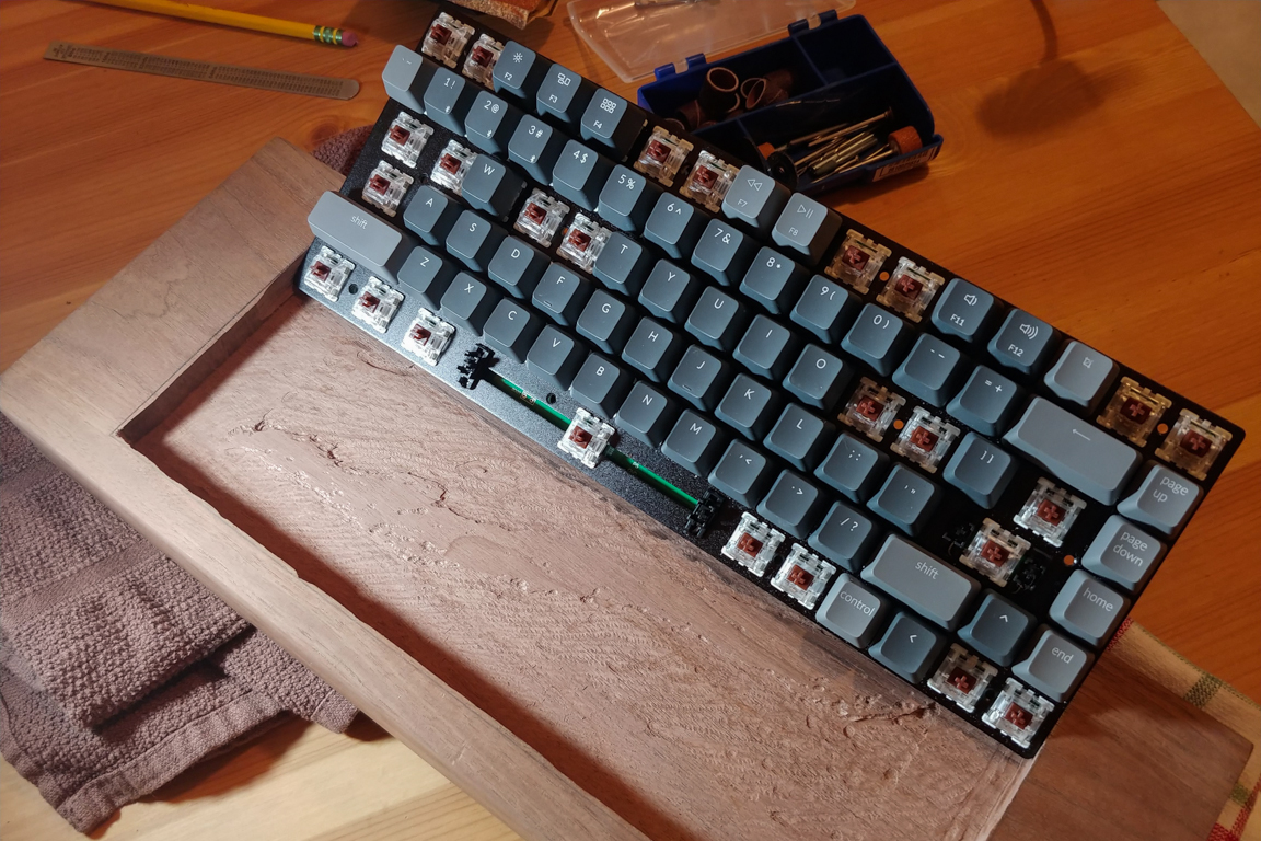
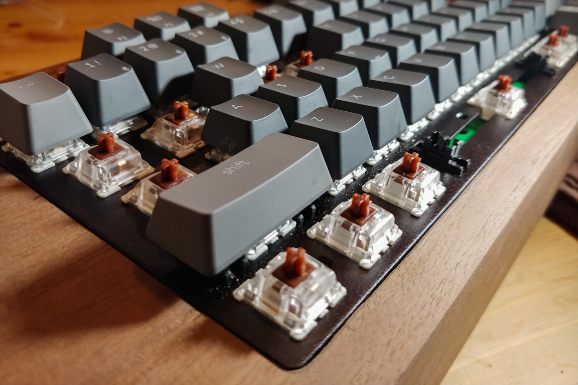
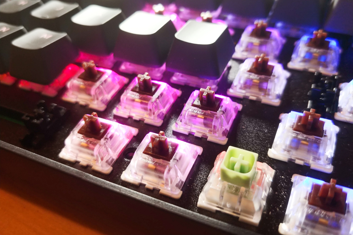
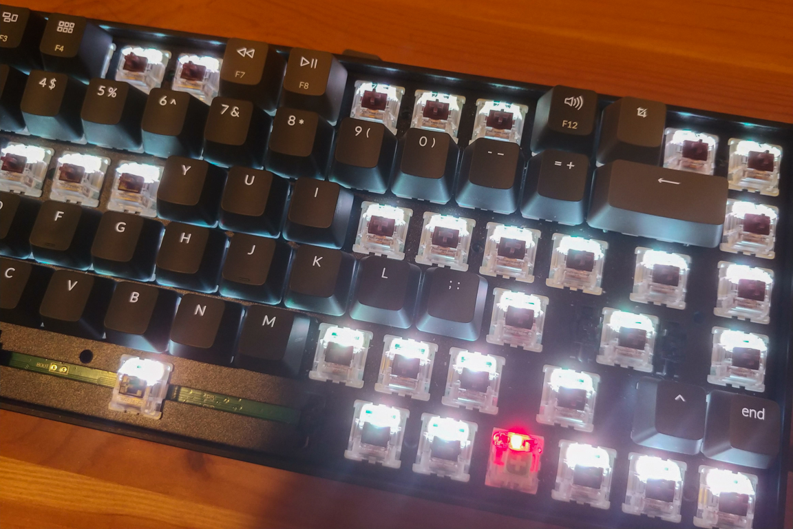
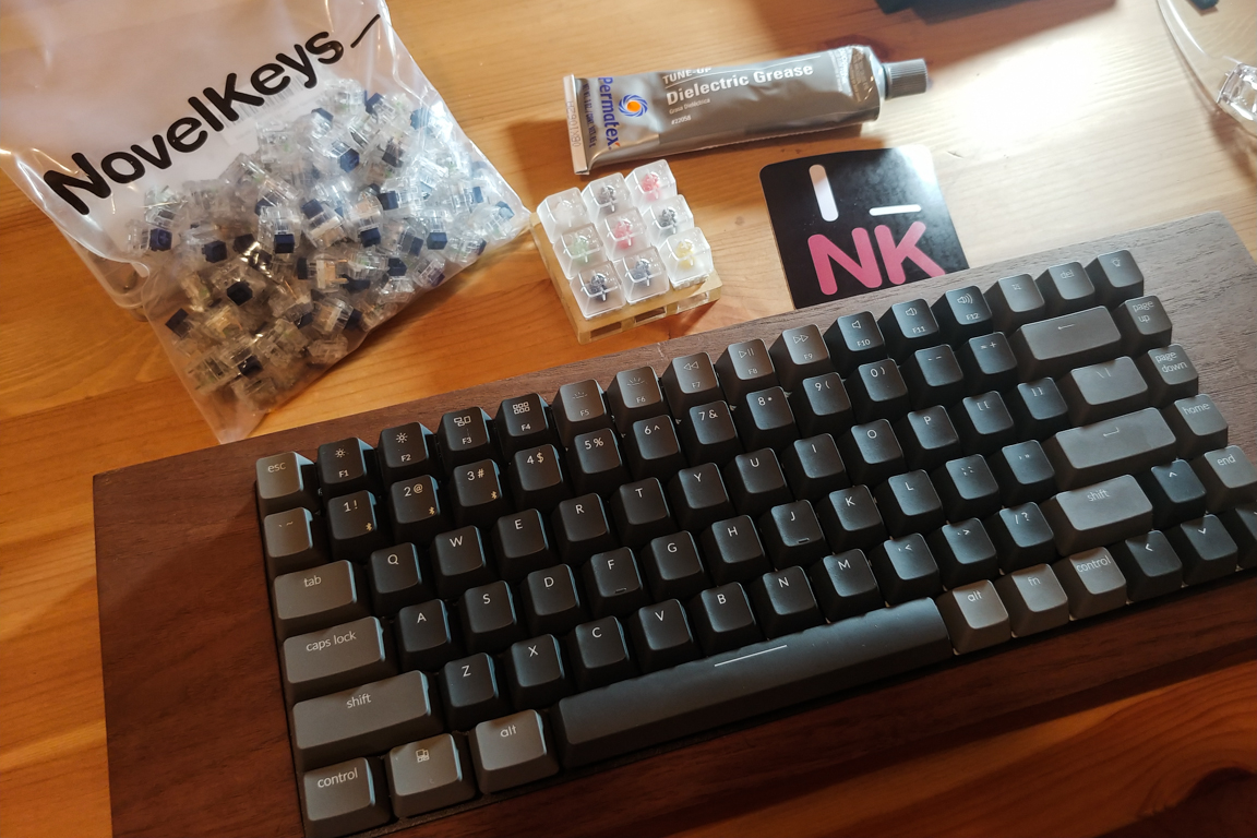
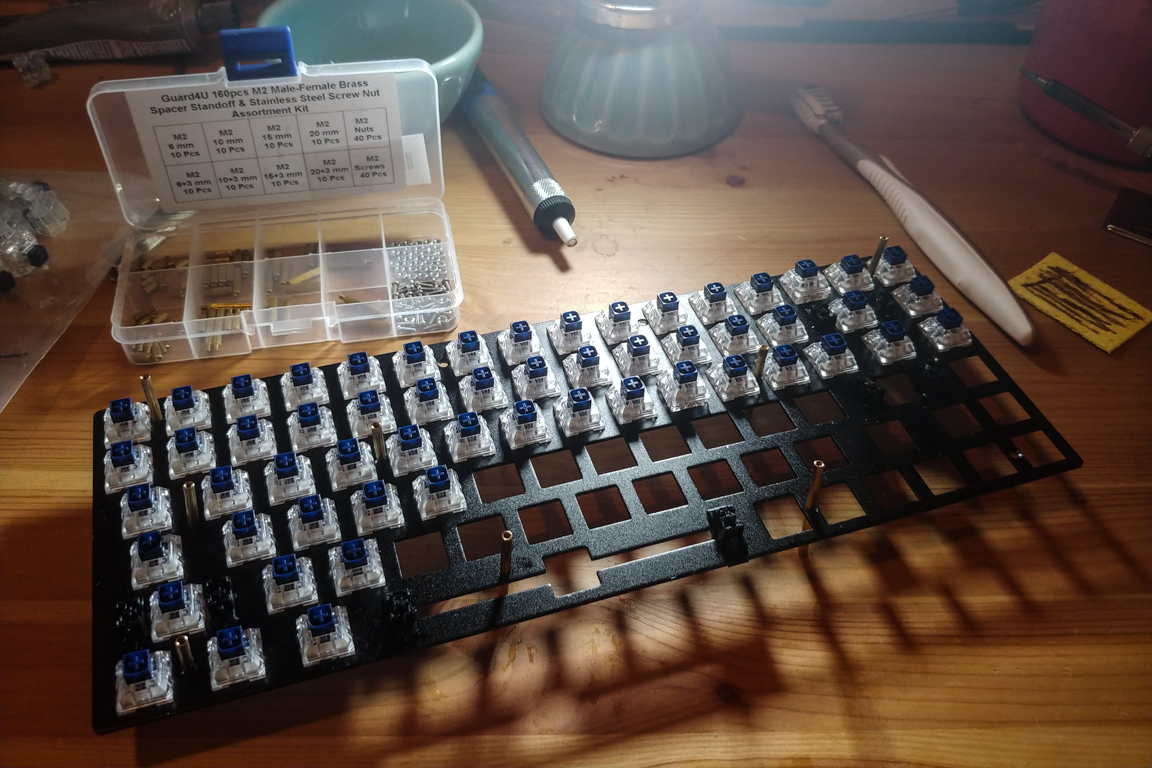
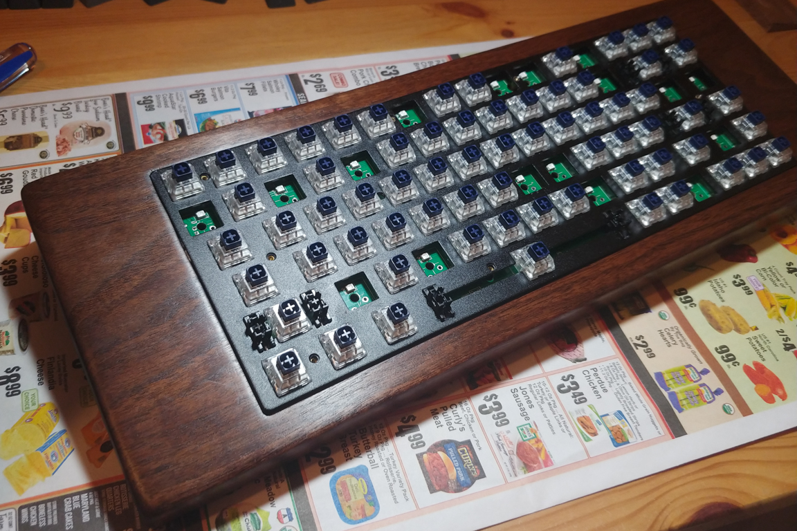
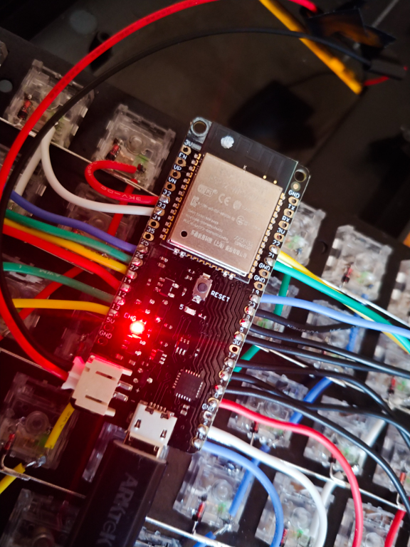
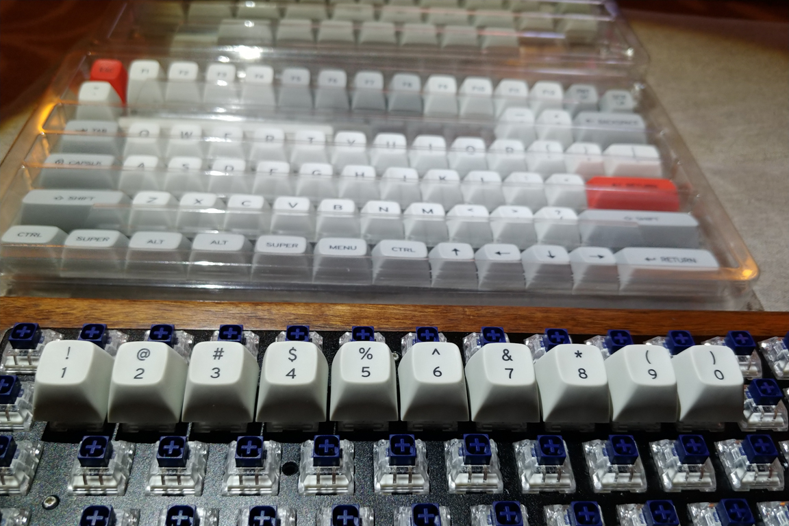
As the week came to an end I received some things I ordered online. As mentioned above I was unhappy with the Gateron switches so I ordered a 9 piece Kailh box testing set. Turns I prefer clicky switches over tactile ones (Gateron Brown). I’m still torn between the Kailh Box Navy or Kailh Box Jades. I soldered off the right control switch and tried replacing it with a Kailh Box Jade switch. I noticed a red light when turning the board on. Turns out the Kailh box switch does not fit into the metal case as easily as the Gateron switch. This is evident in this picture. The bottom left switch is the stock Gateron switch and all other switches are Kailh Box ones. You can see the Kailh switches having curved housings. This curvature damaged the LED light when inserting the switch into the metal housing. Luckily I was able to fix the LED. I think I’ll need to desolder all the switches in order to install the new ones into the metal plate. I ordered a set of Box Crystal Navy switches after a recommendation from a user in this thread. I’m excited.
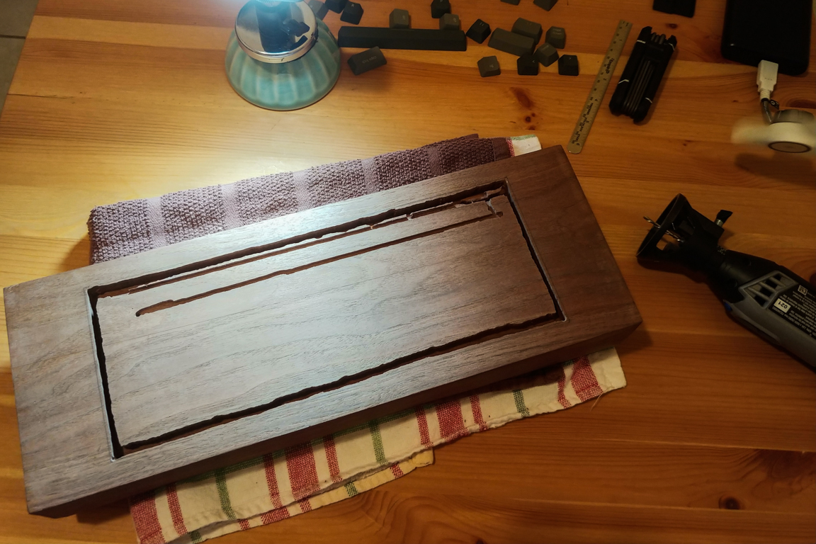
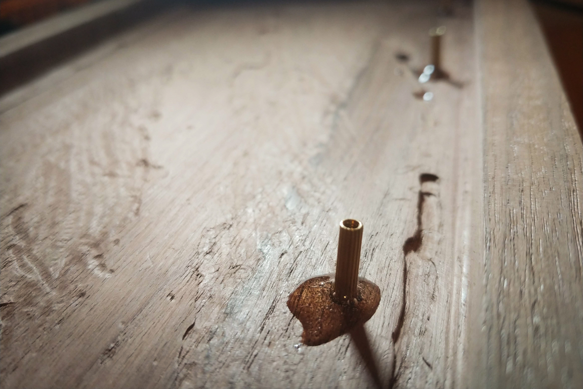
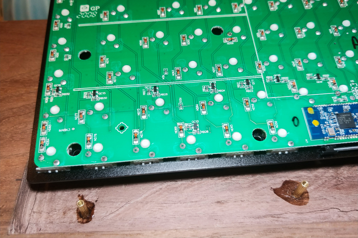
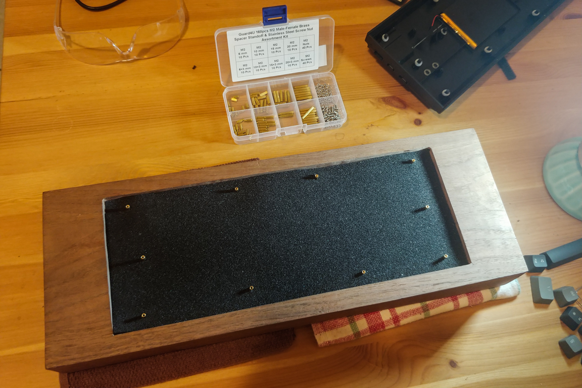
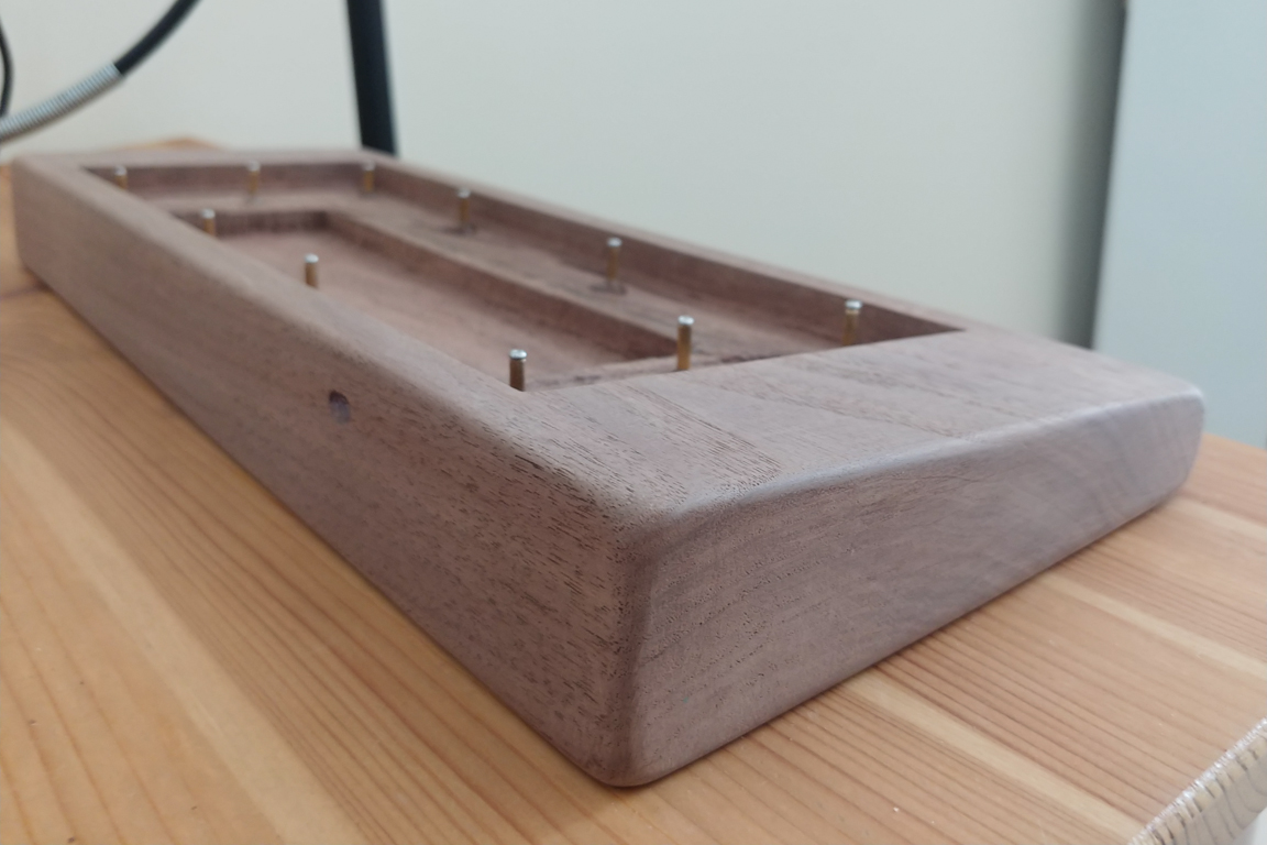
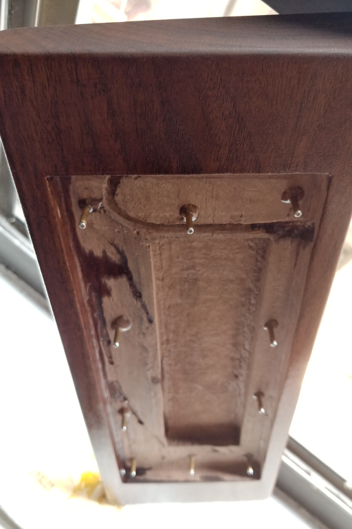
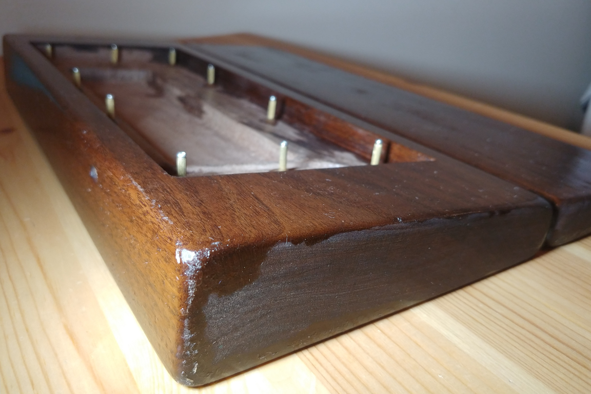
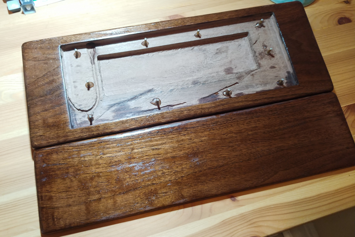
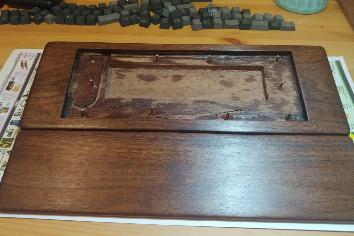
I also received M2 Brass standoffs in the mail. I drilled some holes to recess the bottom four posts into the wooden frame and held it together using epoxy.
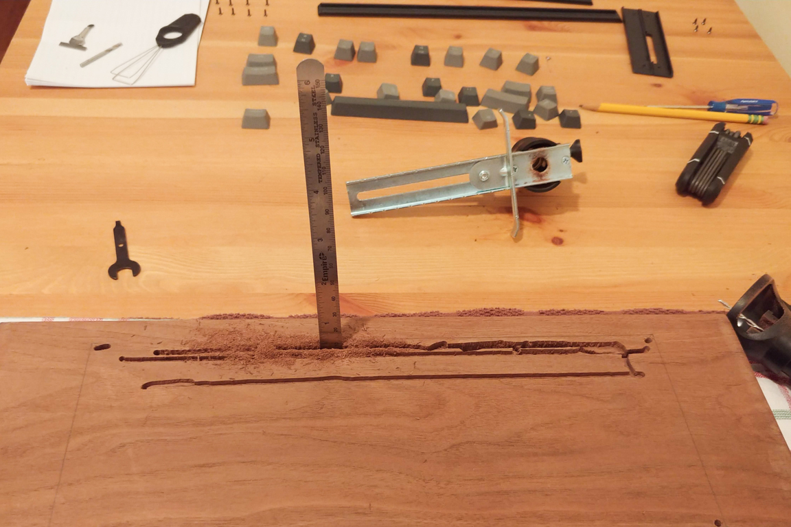
I ran into another setback. I had some ideas about how I will power this new board and concluded that using a usbc extension cable was my best bet. However, when plugged in, the cable protrudes into the side of the frame. I’ll have to cut the following outline into the side of the frame while leaving maintaining a 5mm gap with the top of the frame. I hope I don’t mess things up.
May 31 (Electrical Systems – Part 2)
The stock Keychron comes with a 4000mAh battery. I wanted moaaar capacity!
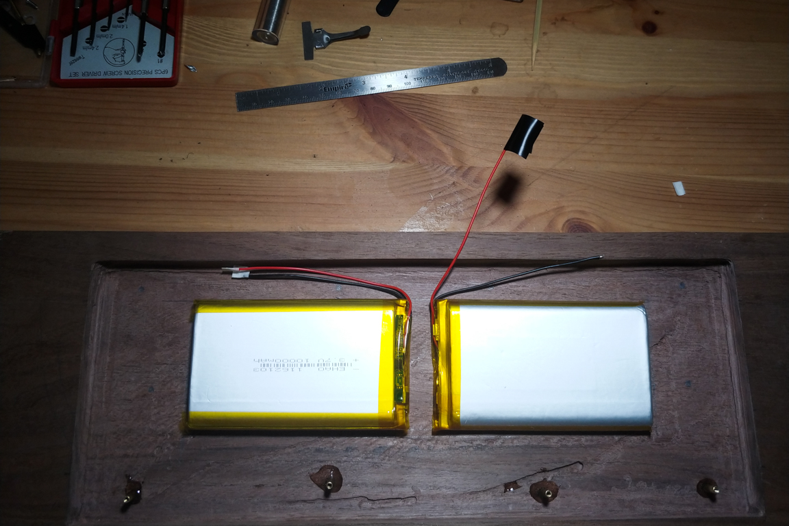
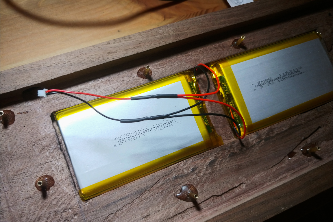
I did some research and then cross checked on Reddit to verify that I could wire two batteries in parallel successfully. I ordered two 10,000mAh batteries and got to work. I initially changed each independently to full capacity. They each took about 12 hours to charge. I’m guessing that in parallel they will take 24 hours?
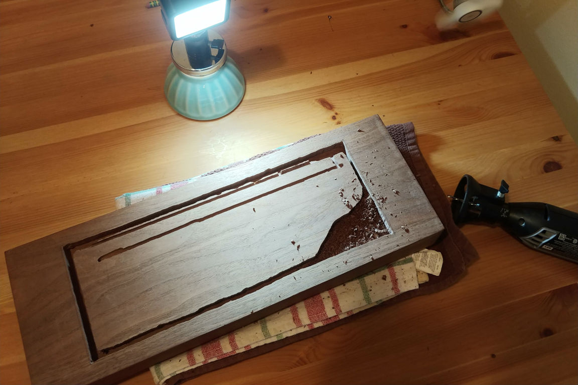
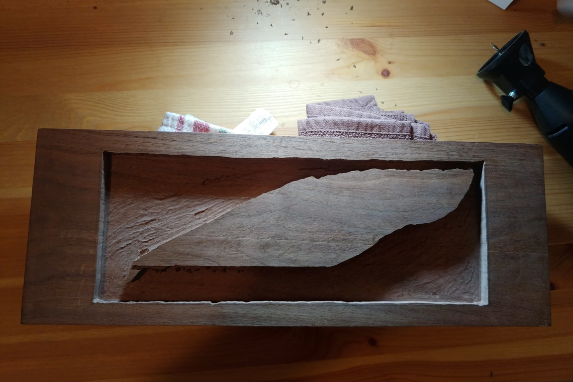
After making the cutouts for the batteries I had to shave a little bit more off the bottom because the padding I was planning to place inbetween the batteries and the keyboard would not fit (without forcing the keyboard down like a full suitcase). I wired the batteries in parallel, used shrink tubing to secure the soldered pieces, and set the batteries aside.
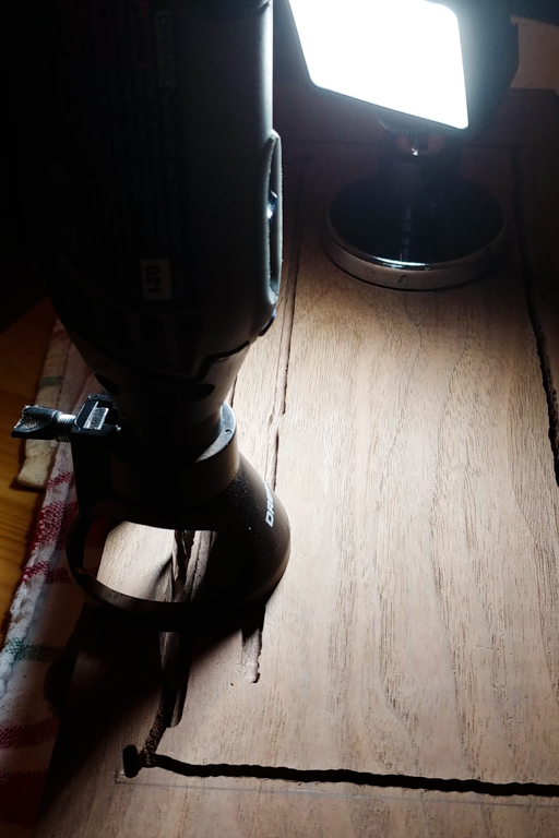
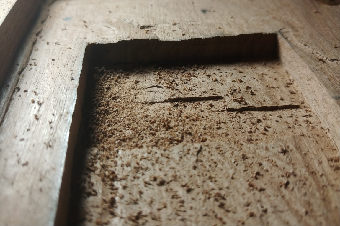
I then tackled something I was putting aside for a while; making a cutout for the USB-C cable. Since the Dremel 4000 was a bit thick so I ended up purchasing the flex shaft to scoop out the side of the board. I ended up scooping about 3/4 of an inch out and that was just enough to get the cable in.
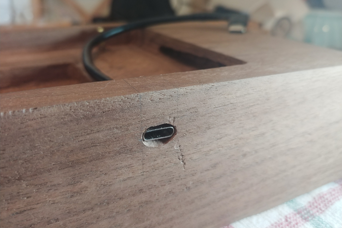
Another thing I was putting off was making the cutout for the USB-C female port. I was debating trying to make this a wireless charging keyboard, but the tolerances needed were too small for my taste. The K2 has a USB-C charging port on the left of the board, but using an adapter I managed to bring the port to the top of the board (between F1 and F2 keys).
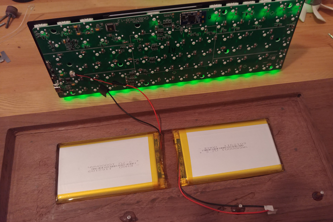
I was able to connect everything together and screw the plate into its new wooden case (with the batteries installed) to witness it working.
June 1 (Progress Pics)
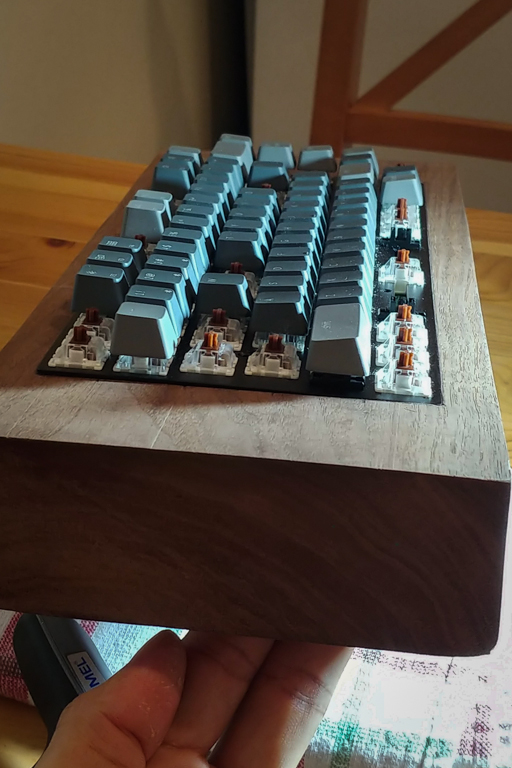
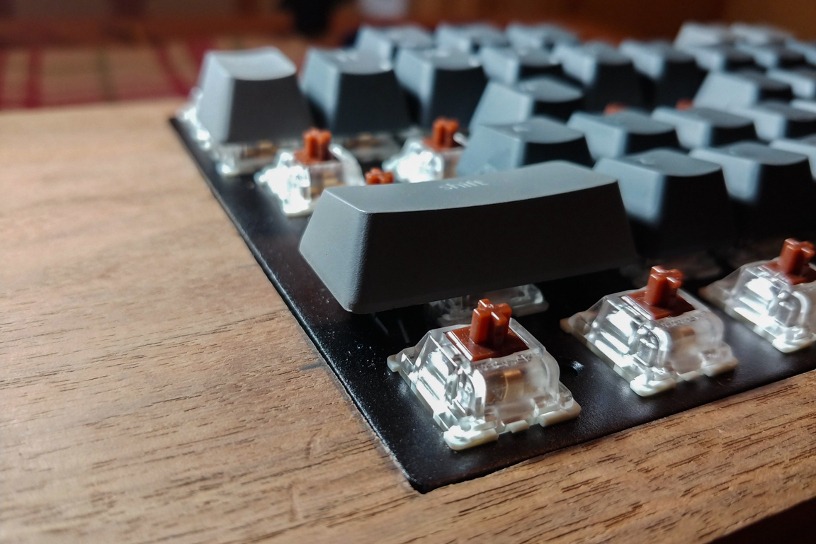
I’ve come a long way with still a while to go. Its been about a month since I stared this project. Why not capture some progress pics of how far I’ve come? Still a bit of woodwork to go but its definitely coming along nicely.
I’m not gonna lie. I have done some typing on this block of wood. My wrists hate me for it, but my heart doesn’t. Things should get better when I cut the block of wood so that it is at an angle facing me. This will also allow me to rest my wrists. Be patient wrists!


June 4 (Desoldering + Soldering)
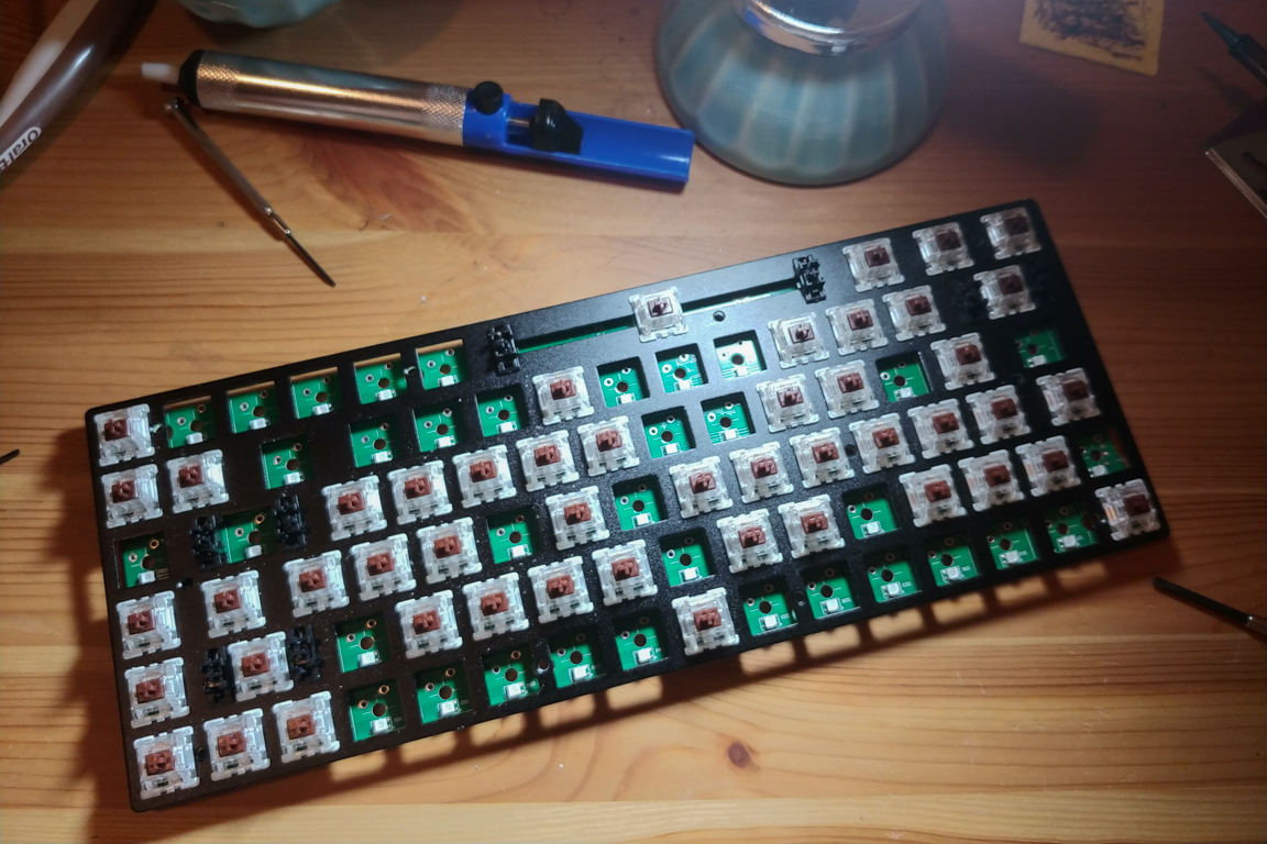
There’s no turning back now. Since I ordered a set of Box Crystal switches I have to desolder the Gateron switches which came with the Keychron K2. Getting the switches off was a bit tough for me. Most of them came off easily but there were some troublemakers.
After about 3 or 4 hours I got all of the switches off and the LEDs on the PCB were still working! However I definitely messed something up in R0 or R1 because after I soldered everything back to together I ended experiencing the below
I tried fiddling around with the soldered joints, but to no avail. I had also destroyed the contacts under the tab button beyond repair. I decided to just purchase a new K2 altogether. I wrote a few emails to Keychron pleading for them to sell me a new PCB (w/o switches) but they insisted I purchase their new K6 which allows for plugging custom switches. No thank you!
June 6 (Wood Working – Part 3)
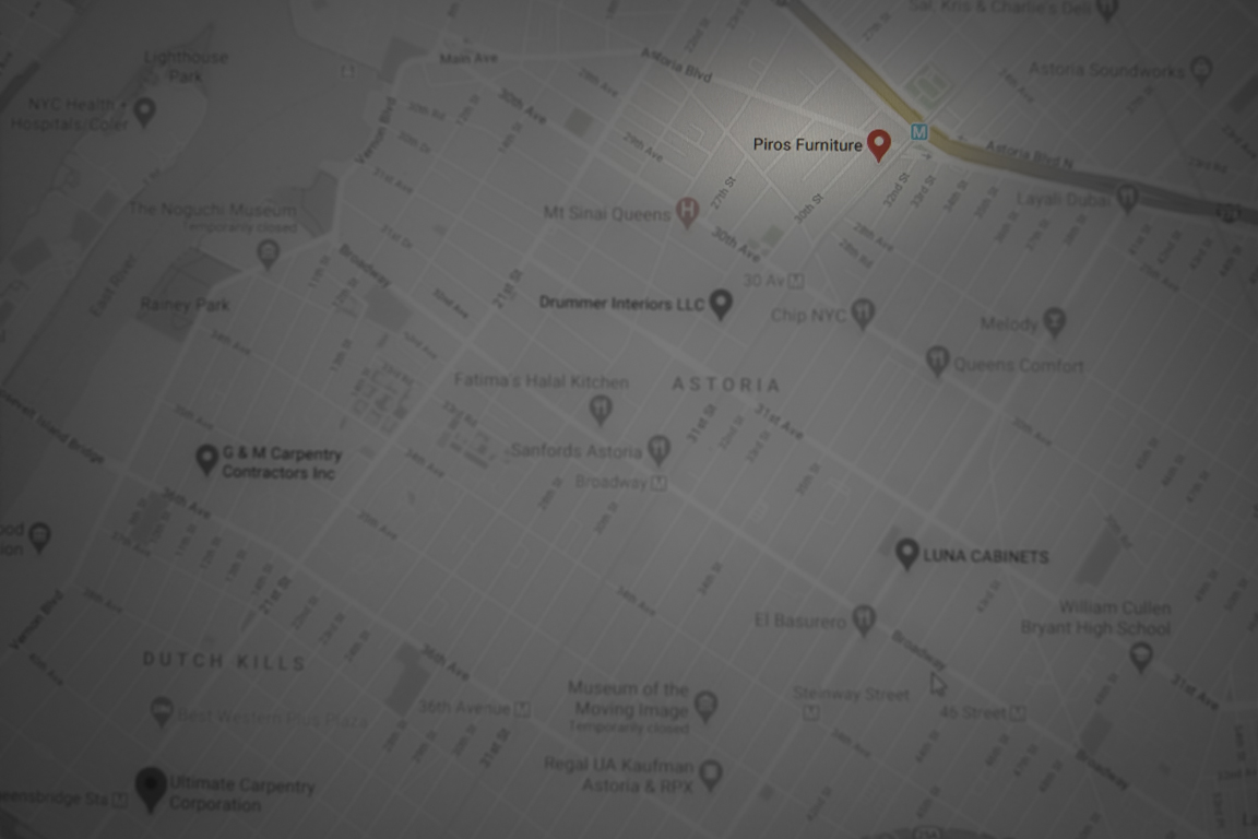
I now needed to cut my block of wood in half (at an angle) in hopes of using the second half as a wrist rest. I initially thought I could use the router and cut the wood down to shape but that would mean I would be losing the bottom half (wrist rest piece) so I looked into other alternatives. I thought I could look around for wooshops in Queens, walk in and ask if they were able to help out. After three shops I stumbled upon Piros Furniture (in Astoria). I walked in, briefly explained what I needed, and someone in the shop helped me out immediately. Did I mention I walked in 10 minutes from closing time? It was amazing how helpful they were. I walked in just trying to get piece of wood cut and walked out with 2 well sanded pieces, some sandpaper, and advice on how to finish the wood. After leaving I checked out they site and they really stand by their claims:
“Piros Furniture aims to create products in an environment that revolves around honesty and rapid solutions. We provide a service with the belief that the process will be as heartwarming as the end result.”
If you are in he New York area and need some woodwork done I would highly recommend them. I only spent about 20 minutes there, but their hospitality and social media (Instagram / Facebook) showcase speaks volumes.
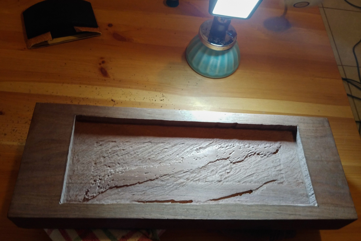
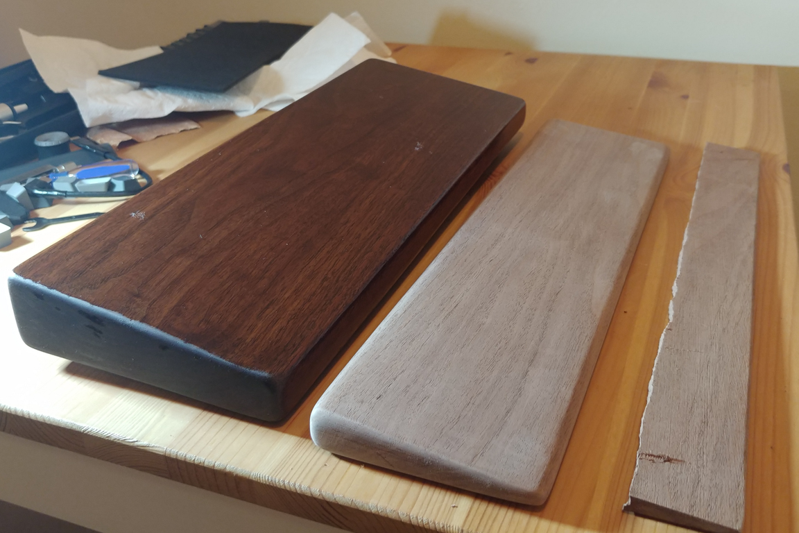
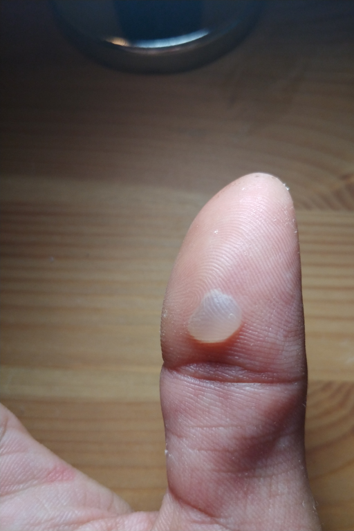
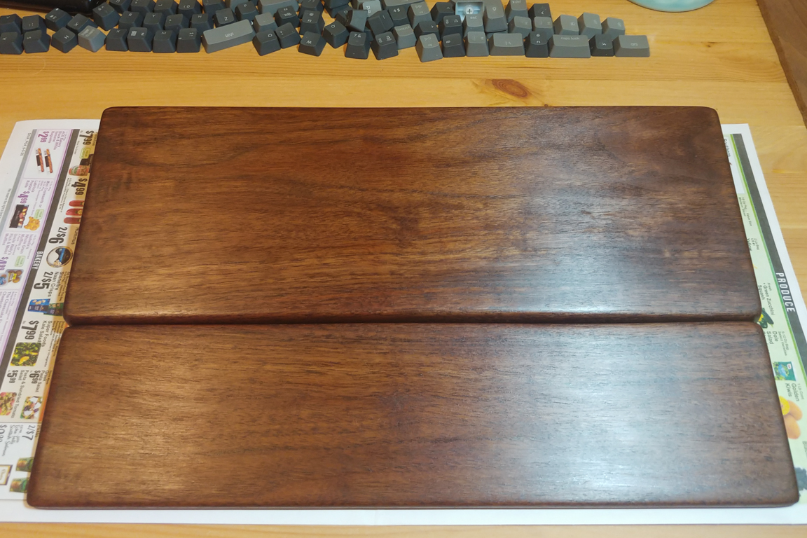
I now had two pieces and needed to do some sanding before applying a coat of Teak Oil. Before applying the teak oil I used the Dremel (wrong tool) to cut about 1.5 inches off the wrist rest. I then applied a moderately heavy coat on the piece holding the PCB. I never wiped the excess off before letting it dry and though it looked fine when drying it looks awful when it dried. There were streaks all over and spots as well. So I had sanded just about everything off and reapplied the oil. I ended up applying roughly 3 coats and walked away with a callus from all the sanding.


June 13 (Putting it all together)
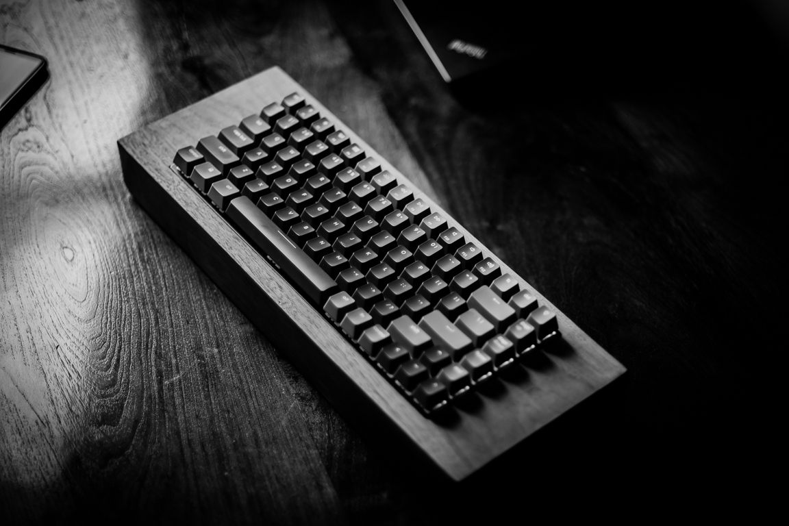
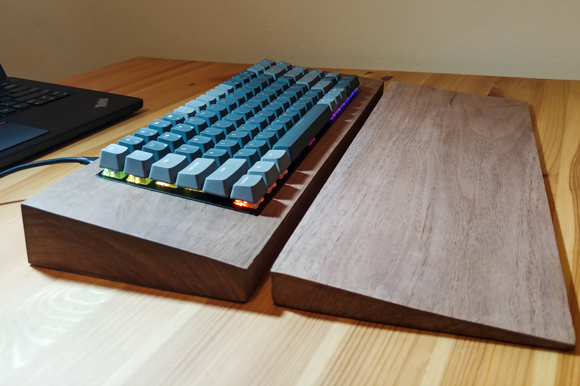
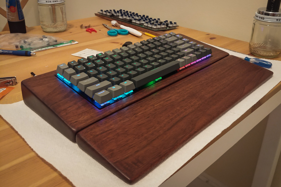
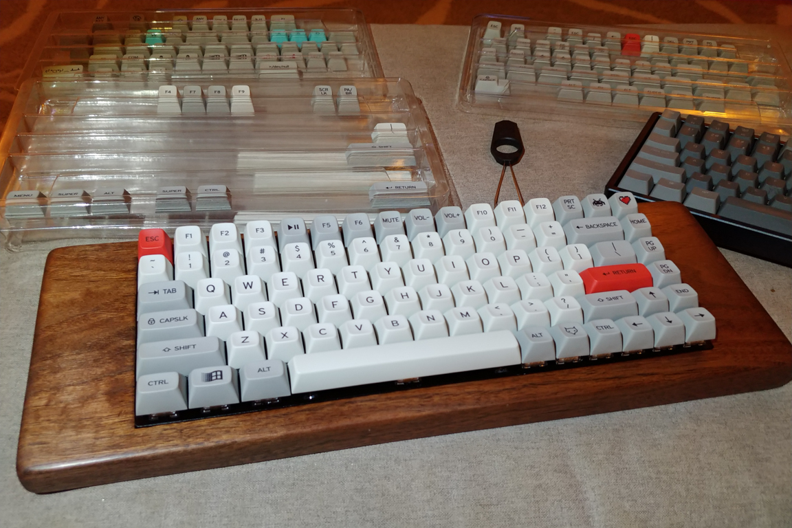
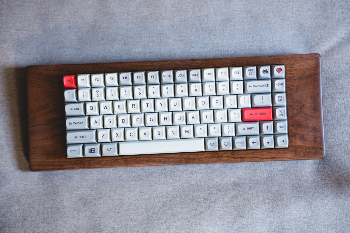
After the Teak Oil dried I applied some Paste wax to protect the wood and apply a nice finish. I love how it ended up looking. Very raw and polished. There are a few scratches here and there (from poor sanding. Pro Tip: Always try to sand with the grain) but overall I am happy with the result. I’m a bit sad I destroyed the original PCB, but at least I had fun doing it. This also gives me an idea to solder the switches together and connect them to a Pro Micro 32u4 board. I’ll lose the LED lighting but I can still bring life to the Box Navy switches.
I cleaned and used the keycaps from the original Keychron. Just wow. Just as I’d hoped the board is heavier and feels great in the hands. The batteries and hard wood complement each other to give the board a solid heavy feel.
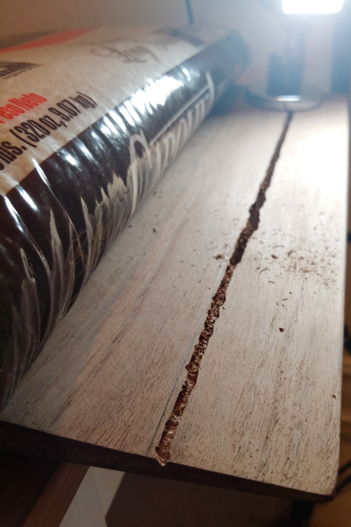
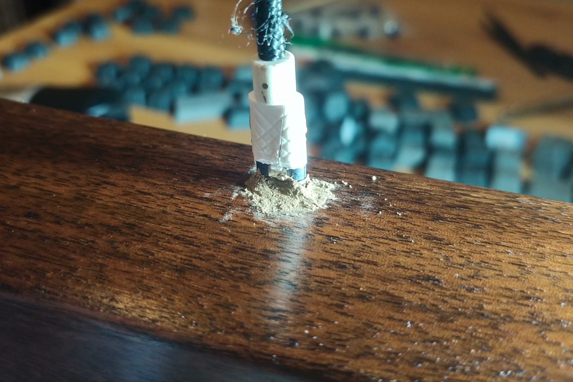
Since the hole cut for the USB-C cable was larger than needed I had to patch it up with some wood filler. I then reapplied oil to that area. I could still see the wood filler after I was done so I decided to purchase some touch-up markers to change the color and it helped a lot.
Now I need to wait for the keycaps to arrive. Ugh. October can you come sooner please?
June 21 (Soldering & Programming)
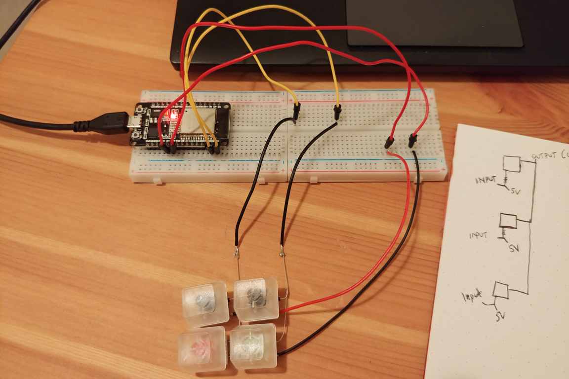
I was a bit disappointing after destroying the PCB from the Keychron K2. I was even more let down now that I couldn’t get my Crystal Navy switches installed in the keyboard. So I decided to take the black metal plate and solder them together. This required some diodes, wire, solder, soldering gun, and a micro controller to piece it all together.
I started off trying to implement a 2×2 keyboard. I found much help from several online postings:
– How to make a keyboard Matrix (sudonull.com)
– Arduino keyboard matrix tutorial (baldengineer.com)
– Handwired Keyboard Build Log (masterzen.fr)
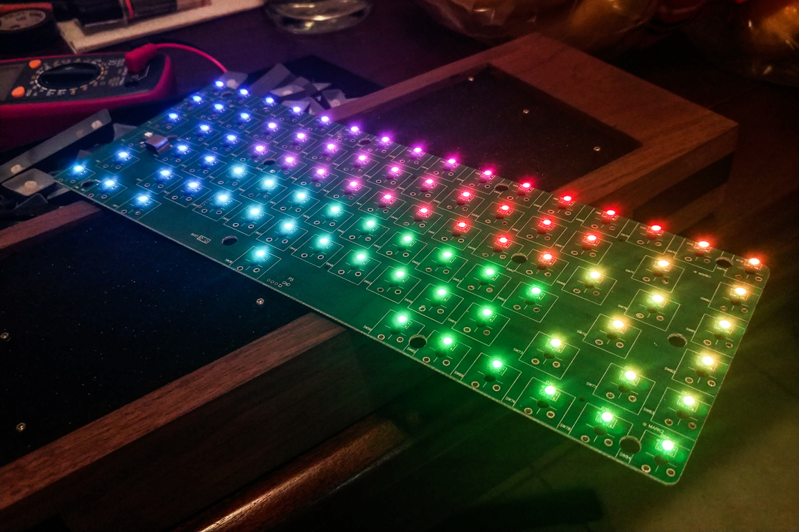
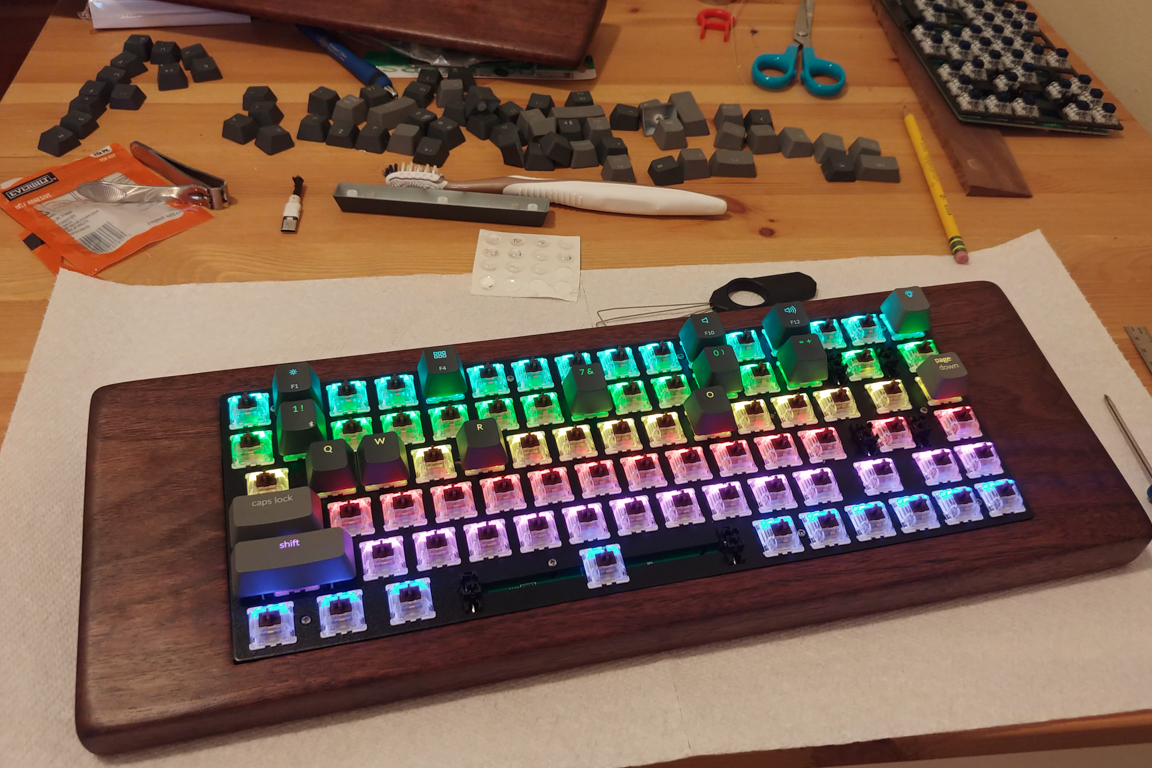
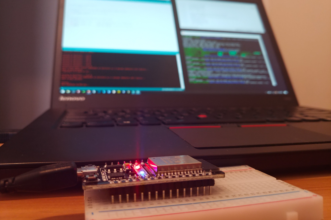
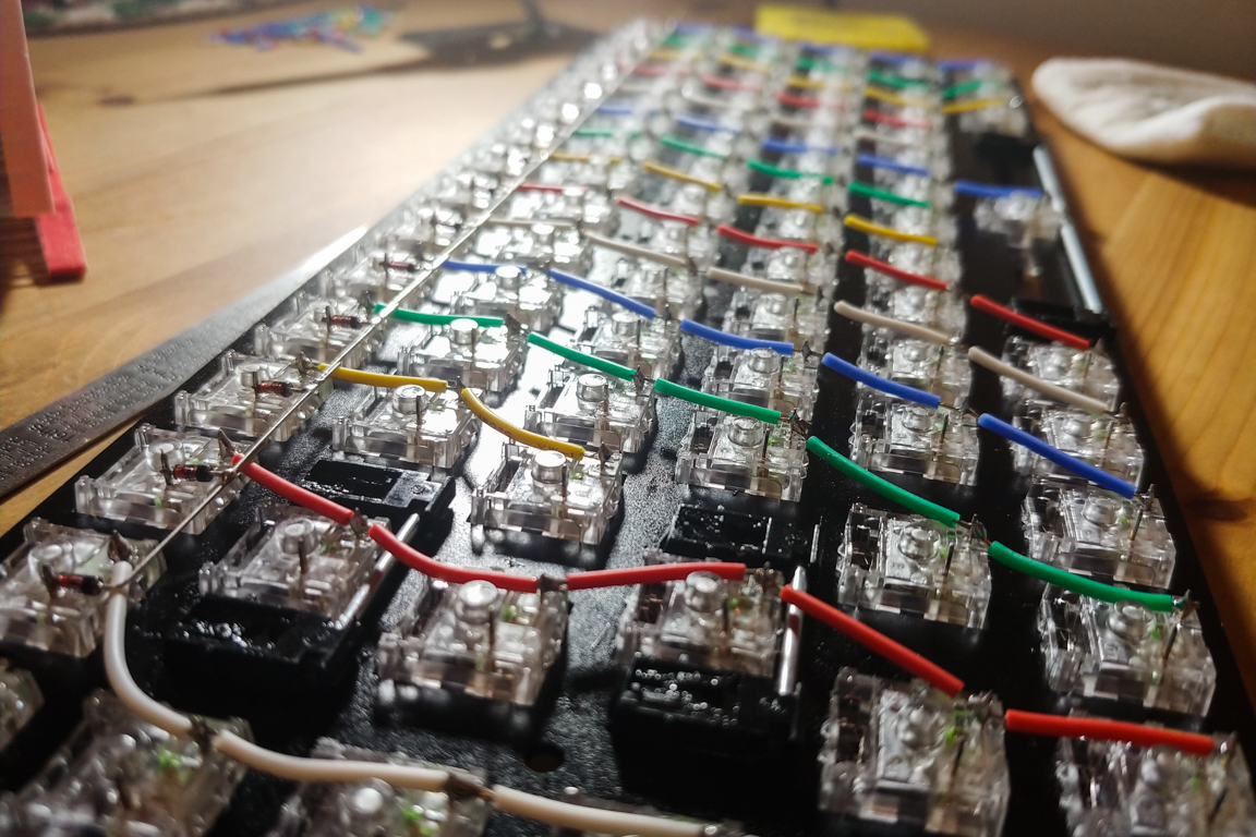
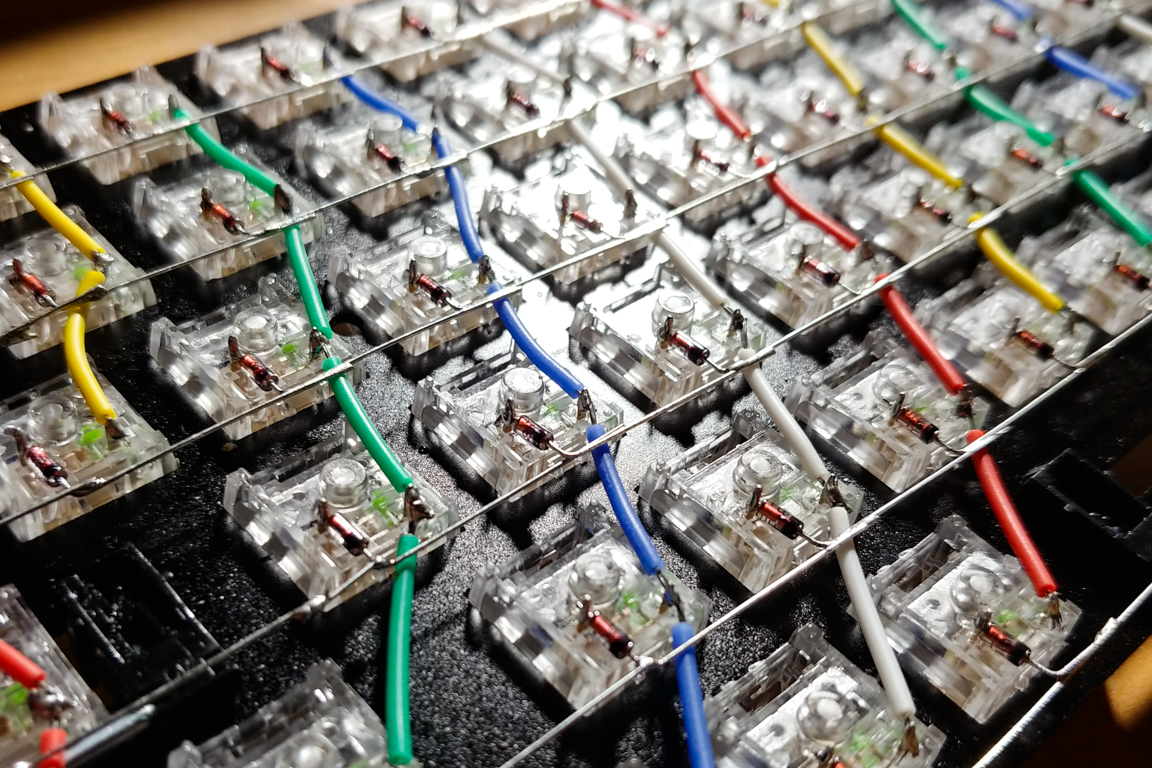
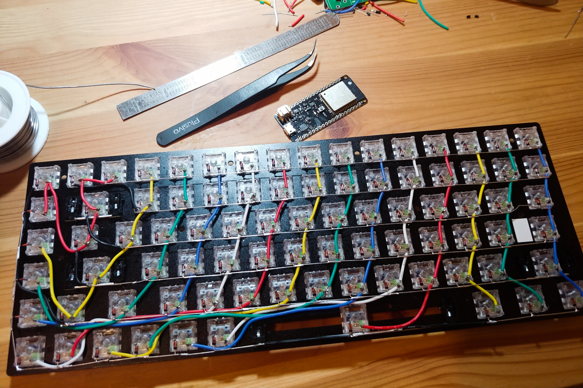
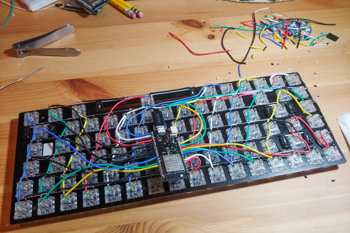
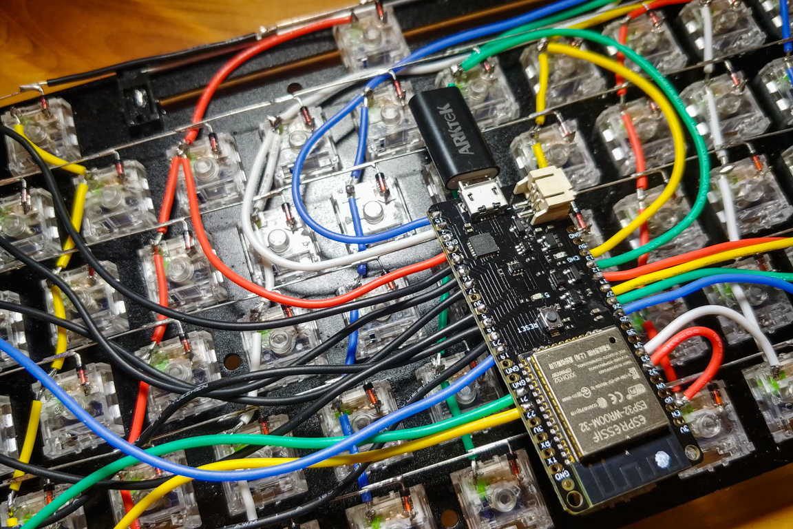
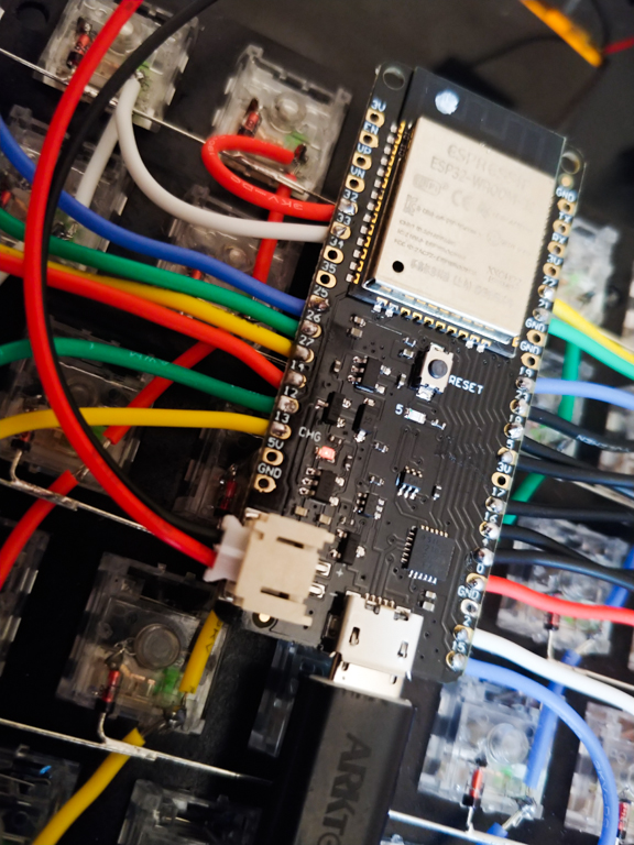
It took a lot of time to wire all the switches together, but the process was very rewarding and visually pleasing. Things started to get messy when I had to connect all the wires over to the ESP32 (microcontroller). But overall I am very happy with the results.
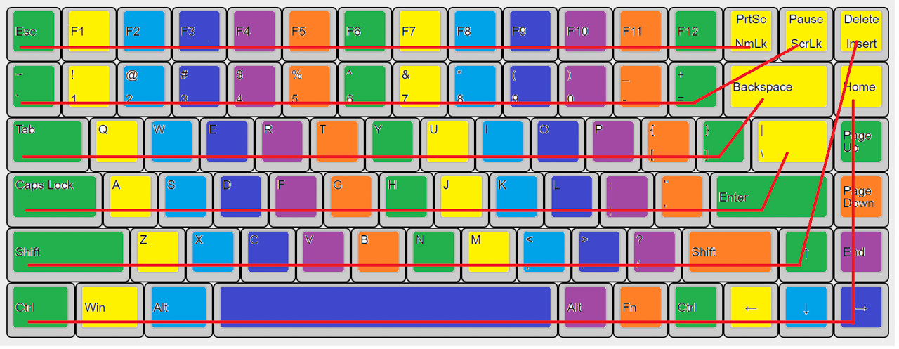
I had used up all 20 GPIO pins on the microcontroller to connect all the rows and columns (14×6). Here’s how I did it. The red horizontal lines represent the rows and the colored squares represent the columns. Each column has exactly 6 keys and each row has 16 keys. This meant the bottom row had to wrap around the corner (Home, PageUp, PageDown, End, Right). I used Arduino IDE to program the micro controller. It took some time but I got it all working.
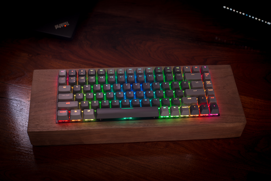
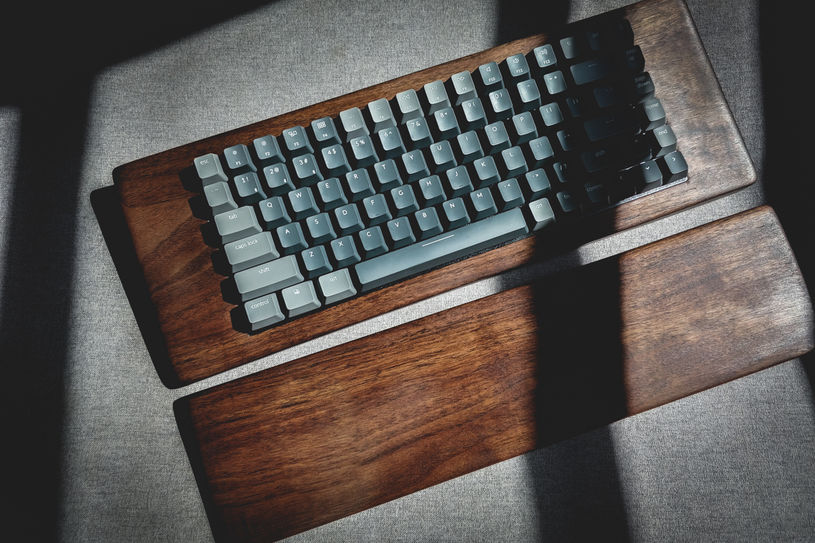
The finished product is starting to look a lot like what I had envisioned when I started building the board. The walnut wood is firm and heavy. I feel the Crystal Box switches complement this characteristic. The clicky switches give the board a typewriter feel (which I hope the MT3 dev/tty switches add to).
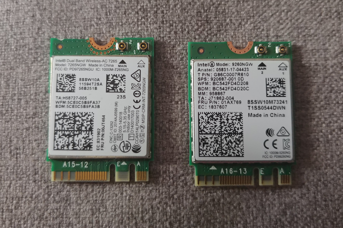
I had a few issues connecting the microcontroller to my laptop. I suspected this might be due to the networking card as there were no issues connecting to my cellphone (Bluetooth 5). So I had ordered an updated card for my laptop. This are working fine now.
I really liked the backlight I had with the Keychron. This made seeing the buttons at night easier. It also allowed user indications for battery percentage. This gave me the idea to order some vibrating motors. However after ordering them I realized I had no spare GPIO ports to use them in. So I ended up constructing a voltage divider and connecting it to a spare GPIO (which was not compatible with the vibrating motor). I now have Fn + B reporting the battery percentage in any text field.
I also want to build out a webpage (as the ESP32 can be used to serve web pages). This gives me something work on as I wait for key keycaps. I also need to touch up the wood a bit as it looks a bit dull in some angles.
November 7 (Feet + Polish)
Wow, its November already? The keycaps were supposed to ship on October 19th but we were notified of a delay (On October 7th):
Hi Everyone, Unfortunately production of these keycaps is running behind schedule. Our manufacturer has pushed back their expected ship date to Nov 15th, which means we’d be shipping towards the end of November. We’ll be posting regular updates in the discussions section as we continue to get more information and more accurate timelines. We appreciate your patience.
Then another one on Oct 19th:
Our manufacturer has pushed back the date, yet again, this time with an expected ship date of Nov 29th, which means we’ll get them around Dec 10th. We’re pushing them to speed up the process (while maintaining quality) and will get back to you with updates as we hear them. Sorry to share the disappointing news.
This is my first time ordering keycaps but I don’t understand why it takes this long to get them manufactured. Oh well!
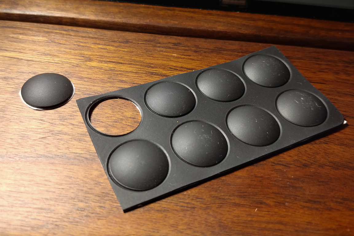
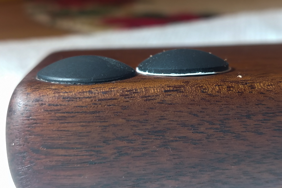
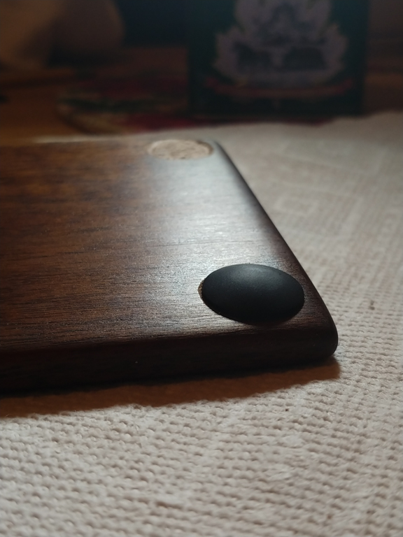
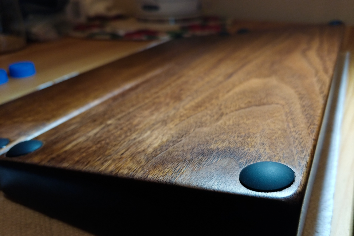
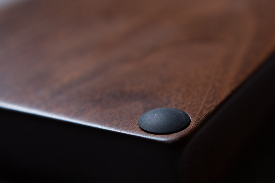
In the meantime I decided to work on the feet of the keyboard and wrist wrest. I was using some cheap circular self adhesive cabinet bumpers. They kept sliding all over the place so I decided improve it.
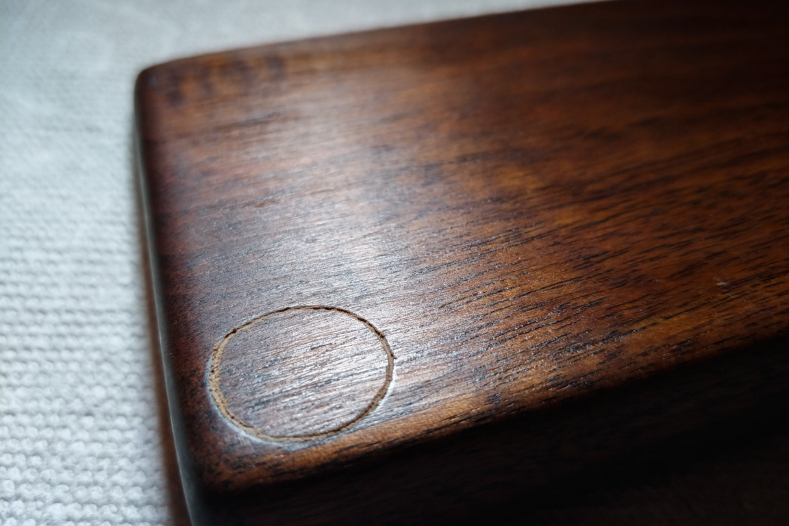
I ordered 8 soft rubber bumpers. I think they are intended for the Macbook but fit perfectly for what I had in mind. Using the Dremel I drilled out 8 0.7inch holes (4 in the keyboard, 4 in the wrist rest). I then used Gorilla Epoxy to glue them in. I gave it 24 hours to dry and they were very firm.
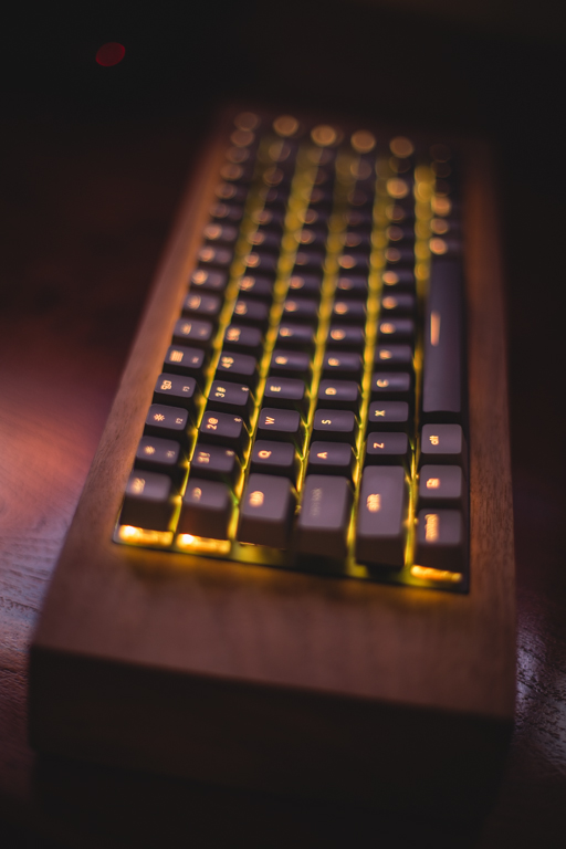
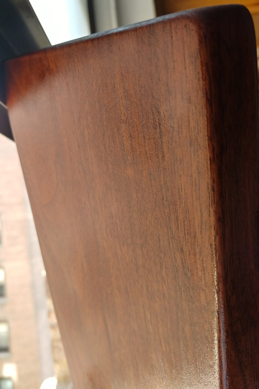
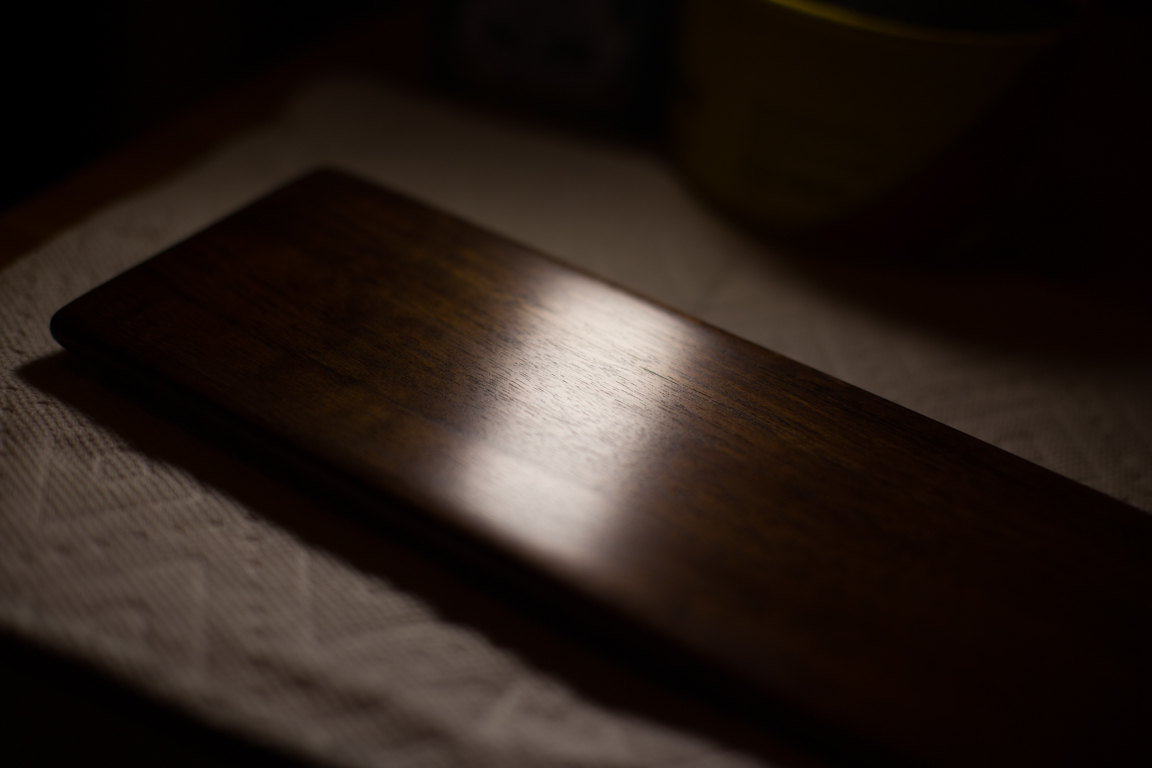
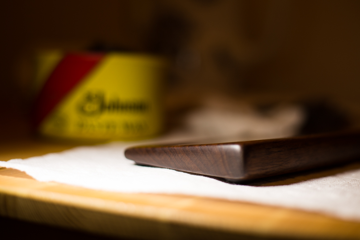
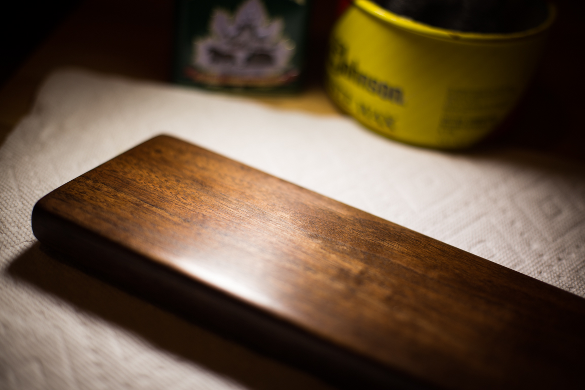
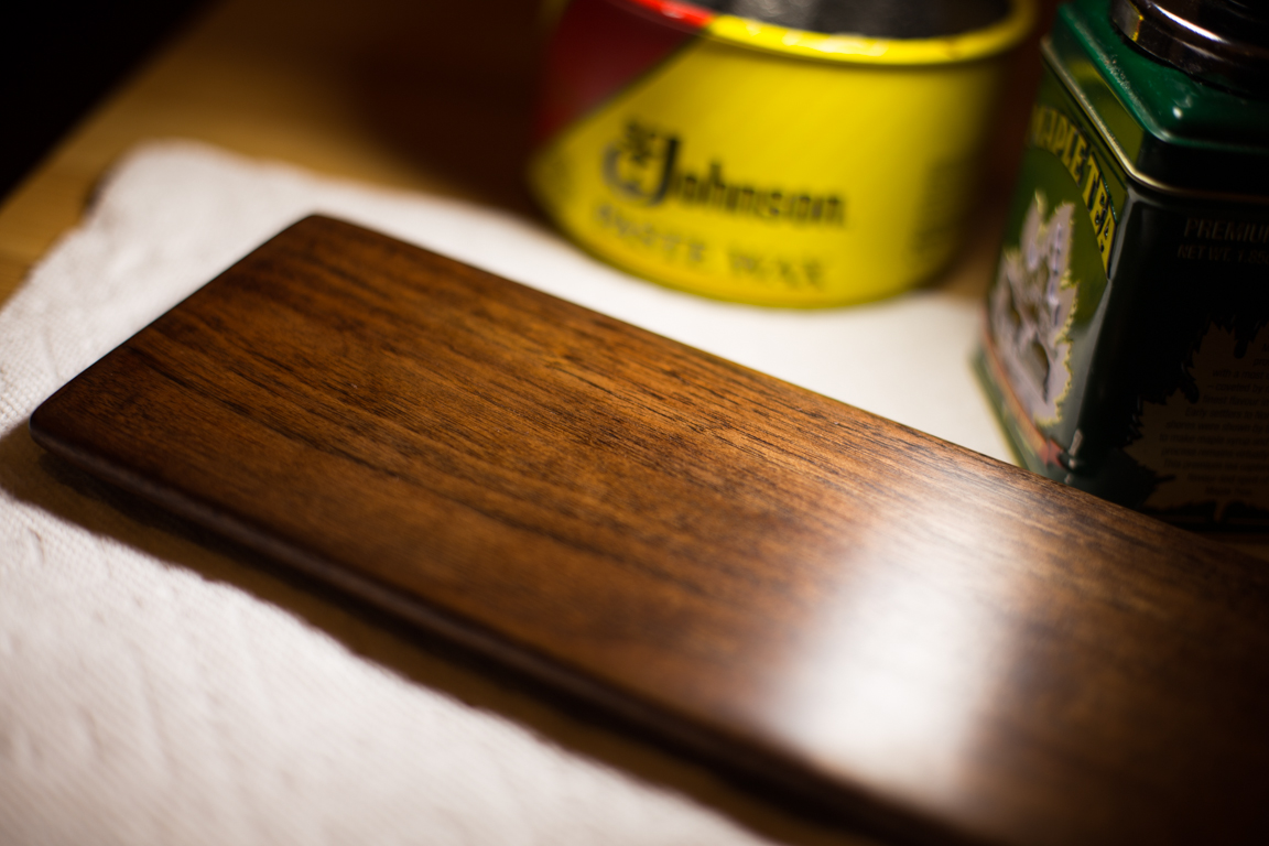
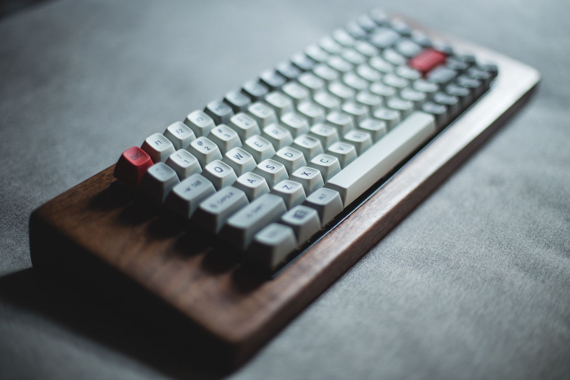
I was dissatisfied with my polishing work, so I took another stab at it. I polished both the wrist rest and keyboard case … all over again and then reapplied another layer of teak oil. I was patient this time and gave it ample time to dry. I then reapplied the left over paste wax giving a bit more elbow grease this time. It payed off! I cannot believe I did this myself! From a dull slab of walnut wood to shiny goodness.
From all the excitement I decided to take some shots of the wrist rest. Though I polished the keyboard case itself as well, I did not take any shots of it now. I will save that for when the keycaps come in.
December 27 (Keycaps Arrive + Sound Testing)
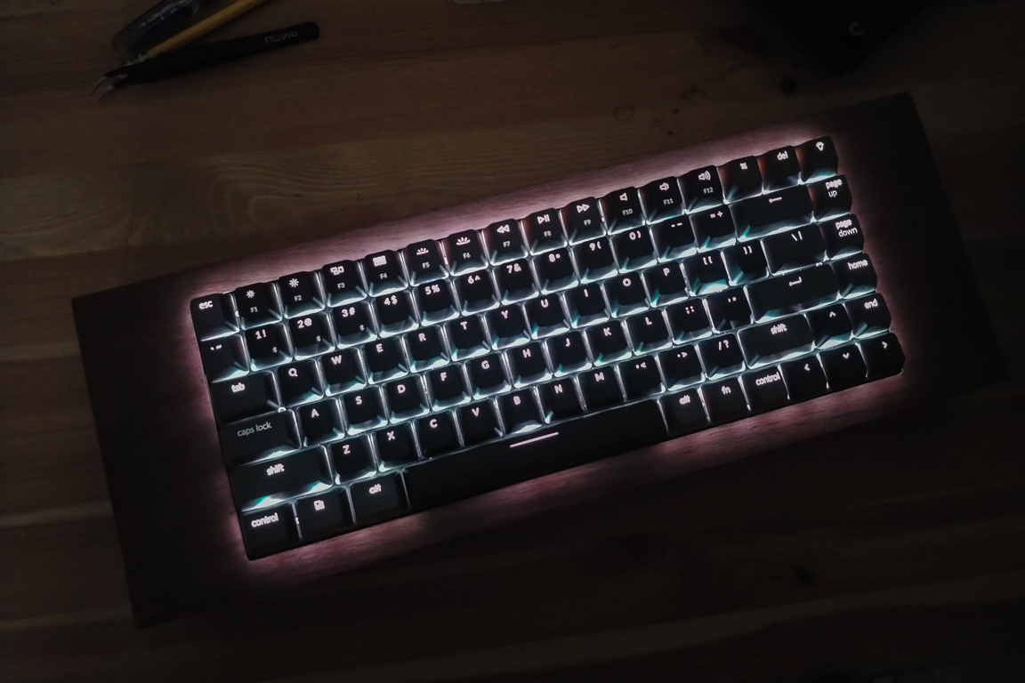
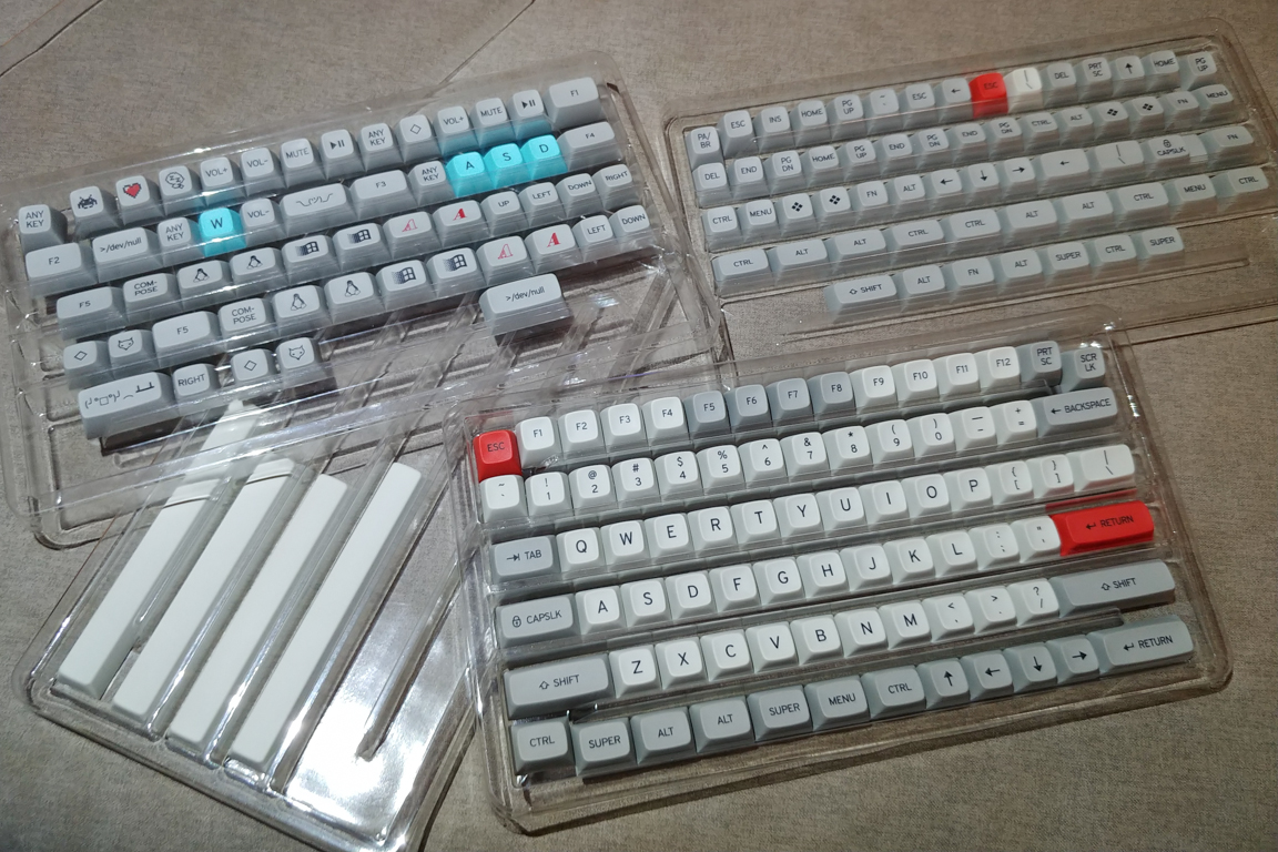
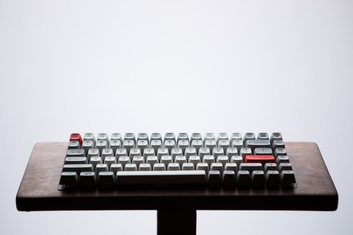
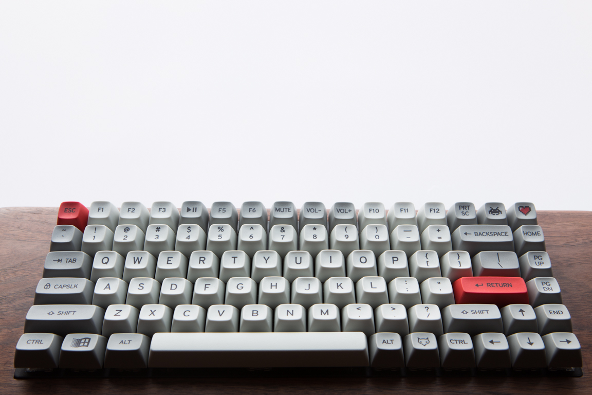
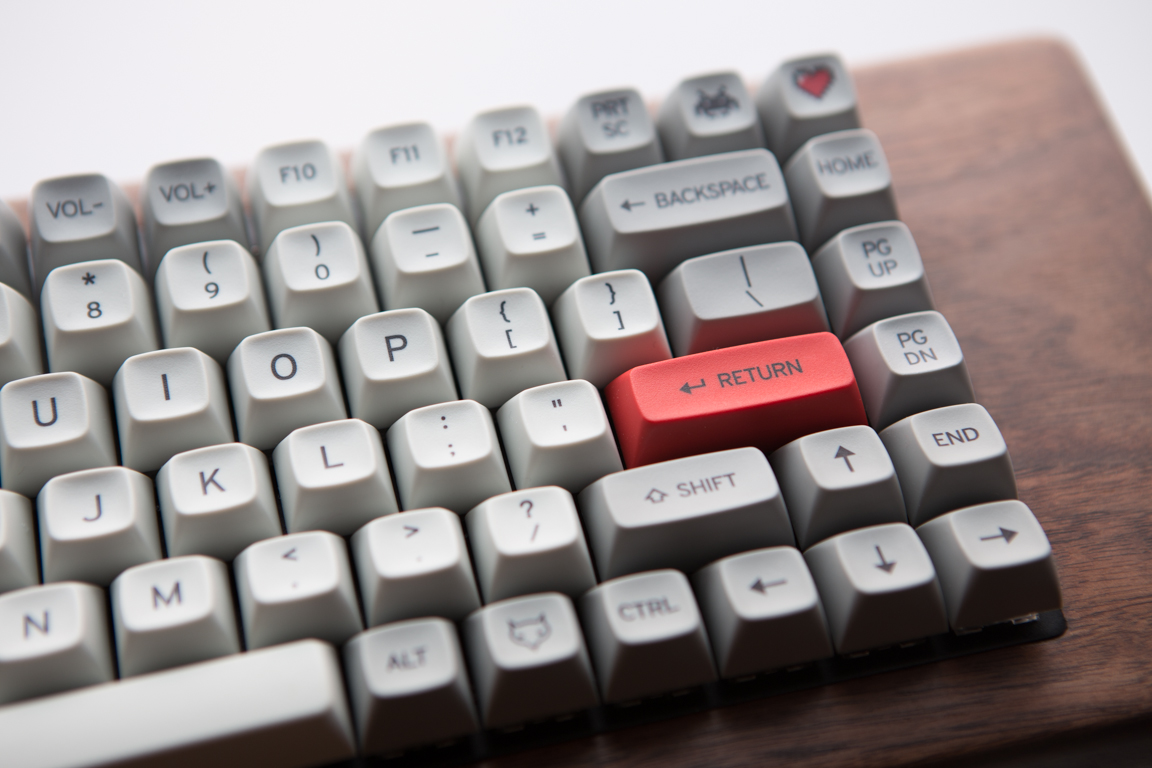
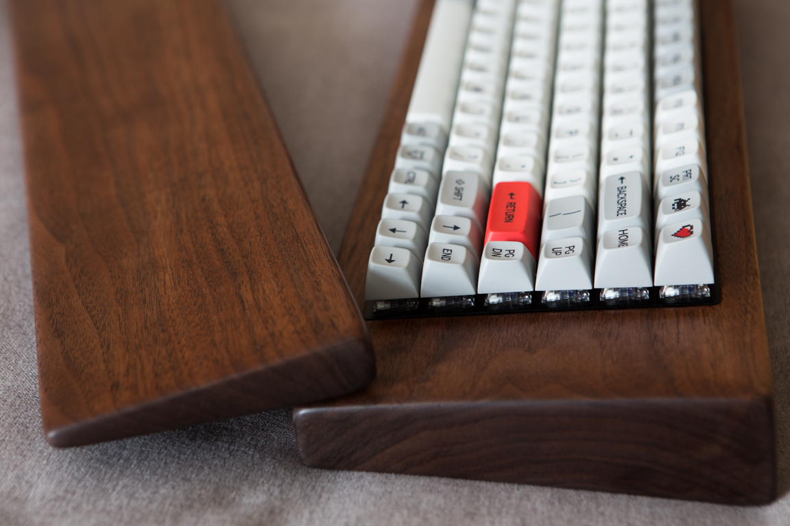
The keycaps are finally here! Took long enough! I guess like they say, “Good things come to those who wait”. Saying they are “good” is an understatement. They are a great improvement over any keycap I have ever used. I started placing them on the switches. The fit was a bit tight but I managed to get them on without any stems cracking (as I have read in some forums).
On to some sound testing. I first gave the keyboard to my wife to test. Thanks for putting up with me for all these months! Thanks for allowing me to turn our apartment’s kitchen into a small wood shop.
I then wanted to take some more standard sound tests I have seen online. I put my camera on a tripod and took this:
Glamour Shots
Tools/Parts
I did get a lot of motivation for this project by the things I saw online. Unfortunately, many of the posts I saw did not list the tools needed or the procedure taken. I’m putting this list together in case it helps someone else out there:
- Wood working
- 6″ scale
- Watco Teak Oil
- Dremel Flex Shaft
- Dremel 4000 39-Piece set
- Gorilla 0.85 fl. oz. Epoxy
- DAP Plastic wood Latex Wood Filler
- SC Johnson 1lb Fine Wood Paste Wax
- Varathane Wood Stain Touch-up Marker Kit
- Guard4U 160pcs M2 Male-Female Brass Hex Spacer
- 3M Garnet 60 Grit Coarse Grade Sandpaper
- 3M Pro Grade Precision 220 Grit Fine Advanced Sanding Sheets
- 3M Pro Grade Precision 400 Grit X-Fine Advanced Sanding Sheets
- Electrical
- Plisivo Soldering Iron Kit
- AstroAI Digital Multimeter
- 2 x 10,000mAh Lithium Polymer batteries
- UseBean 90 Degree USBC Extension Cable
- ESP32 ESP-WROOM-32 Wemos D1 LOLIN32 WIFI+BT 2.4GHz
- TUOFENG 26 AWG Stranded Wire Kit-Flexible Silicone Wire
- EDGELEC 100pcs 1K ohm Resistor 1/2w (0.5Watt) ±1%
- Chanzon 1N4148 Diodes 200mA 100V 100pcs
- Keyboard
- 2 x Keychrok K2 RGB – Gateron Brown
- Drop + Matt3o /dev/tty MT3
- 90 Box Crystal Navy Switches
- 9 Key Kailh Box Switch Tester
- UOTOO 8 Pcs Laptop Rubbe Feet (0.7 inch Diameter)